OPERATION • MAINTENANCE • REPAIR PARTS LIST PPT POWERED PALLET TRUCK PPT SERIES [PPT_40-0278] 2/2
This article provides a comprehensive list of operation, maintenance, and repair parts for the DP PPT Series powered pallet truck, enabling users to easily find the necessary components for their trucks.

Written by Nash Bernardo
Updated at July 29th, 2025

TECHNICAL MANUAL
POWERED
PALLET
TRUCK
PPT SERIES
TABLE OF CONTENTS | |||||
SECTION |
|
PAGE |
SECTION |
|
PAGE |
|
PREPARATION FOR USE |
1-1 |
III |
MAINTENANCE AND MAINTENANCE PARTS (CONTINUED) |
|
I |
DESCRIPTION |
1-2 |
3-5 |
Battery Care |
3-2 |
1-1 |
Introduction |
1-2 |
3-6 |
Lubrication |
3-2 |
1-2 |
Description |
1-2 |
3-7 |
Troubleshooting |
3-4 |
1-3 |
General |
1-2 |
3-8 |
Adjustment and Repair |
3-8 |
1-4 |
Capabilities |
1-2 |
3-9 |
Belly-Button Safety Switch Adjustment |
3-8 |
1-5 |
Safety Features |
1-2 |
3-10 |
Control Head Switch Replacement |
3-8 |
1-6 |
Options |
1-2 |
3-11 |
Steering Arm |
3-10 |
II |
OPERATION |
|
3-12 |
Electrical Control Cable Replacement |
3-12 |
2-1 |
General |
2-1 |
3-13 |
Mechanical Brakes |
3-13 |
2-2 |
Operating Precautions |
2-1 |
3-14 |
Drive Motor Repair |
3-17 |
2-3 |
Driving and Stopping |
2-1 |
3-15 |
Chassis and Pivot Assemblies |
3-17 |
2-4 |
General |
2-1 |
3-16 |
Wheel Housings and Exit Rollers |
3-28 |
2-5 |
Driving and Stopping Procedures |
2-2 |
3-17 |
Saucer Assembly and Caster Replacement |
3-29 |
2-6 |
Belly-Button Safety Guard |
2-3 |
3-18 |
Load Wheel Replacement |
3-30 |
2-7 |
Dynamic Brake |
2-3 |
3-19 |
Transmission Repair |
3-30 |
2-8 |
Steering Arm Return Spring |
2-3 |
3-20 |
Drive Wheel Replacement |
3-31 |
2-9 |
Various Stopping Methods |
2-3 |
3-21 |
Hydraulic System Repair |
3-34 |
2-10 |
Operating Lift |
2-3 |
3-22 |
Hydraulic Pump-Motor-Reservoir Assembly |
3-36 |
2-11 |
Loading and Unloading |
2-3 |
3-23 |
Lift Cylinder Repair |
3-38 |
2-12 |
Parking |
2-3 |
3-24 |
Contactor Tip Replacement |
3-40 |
III |
MAINTENANCE AND MAINTENANCE PARTS |
|
3-25 |
Speed Control Resistor Adjustment |
3-40 |
3-1 |
General |
3-1 |
3-26 |
Battery Connector Group Replacement |
3-45 |
3-2 |
Part Number Identification |
3-1 |
3-27 |
Metal Service Cover |
3-45 |
3-3 |
Preventive Maintenance |
3-1 |
|
||
3-4 |
Inspection and Service |
3-1 |
|||
LIST OF ILLUSTRATIONS | |||||
Figure |
|
Page |
Figure |
|
Page |
1-1 |
Powered Pallet Truck, Model PPT-40 |
1-2 |
3-20 |
Hydraulic System (Serial Number 81936 and Lower) |
3-34 |
2-1 |
Steering Arm Controls |
2-1 |
3-21 |
Hydraulic System (Serial Number 81937 and Higher) |
3-35 |
2-2 |
Speed Control |
2-1 |
3-22 |
Pump-Motor-Reservoir Assembly (Serial Numbers 81936 and Lower) |
3-36 |
2-3 |
Mechanical Brake Application |
2-2 |
3-23 |
Pump-Motor-Reservoir Assembly (Serial Numbers 81937 and Higher) |
3-37 |
3-1 |
Lubrication Points |
3-3 |
3-24 |
Lift Cylinder P/N 047552 |
3-38 |
3-2 |
Schematic Diagram |
3-7 |
3-25 |
Lift Cylinder P/N 047564 |
3-39 |
3-3 |
Belly-Button Safety Switch Adjustment |
3-8 |
3-26 |
70-Amp Contactor Wire Terminations |
3-40 |
3-4 |
Control Head |
3-9 |
3-27 |
70-Amp Contactor Tip Replacement |
3-41 |
3-5 |
Pivot Tube and Steering Arm |
3-11 |
3-28 |
Electrical Control Components and Battery Connector Group (Serial Number 67146 to 70874) |
3-42 |
3-6 |
Electrical Control Cable Replacement |
3-12 |
3-29 |
Contactor Panel (Serial Number 70875 and Higher) |
3-43 |
3-7 |
Mechanical Brake Adjustment |
3-13 |
3-30 |
Speed Control Resistor Assembly (Serial Number 70875 and Higher) |
3-44 |
3-8 |
Drum Brake and Linkage |
3-15 |
3-31 |
Battery Connector Group and Horn (Serial Number 70875 and Higher) |
3-45 |
3-9 |
Disk Brake and Linkage |
3-16 |
3-32 |
Metal Service Kit Bracket |
3-46 |
3-10 |
Drive Motor |
3-17 |
3-33 |
Bracket and Cover Drilling |
3-46 |
3-11 |
Standard Chassis and Pivot Assembly (Eccentric Adjusted Push Rods) |
3-22 |
3-34 |
Tapping Diagram |
3-46 |
3-12 |
Standard Chassis and Pivot Assembly (Universal Push Rods) |
3-24 |
3-35 |
Service Cover Assembly |
3-46 |
3-13 |
Narrow Straddle Chassis and Pivot Assembly |
3-26 |
|
||
3-14 |
Straddle and Pivot Blocks |
3-28 |
|||
3-15 |
Modification of Wheel Housing Casting |
3-29 |
|||
3-16 |
Special Length Push Rods |
3-29 |
|||
3-17 |
Caster Assembly |
3-30 |
|||
3-18 |
Tandem Load Wheels |
3-31 |
|||
3-19 |
Transmission and Drive Wheel |
3-32 |
|||
LIST OF TABLES | |||||
Table |
|
Page |
Table |
|
Page |
3-1 |
Inspection and Service Chart |
3-1 |
3-3 |
Lubrication |
3-3 |
3-2 |
Recommended Lubricants |
3-2 |
3-4 |
Troubleshooting Chart |
3-4 |
continued…
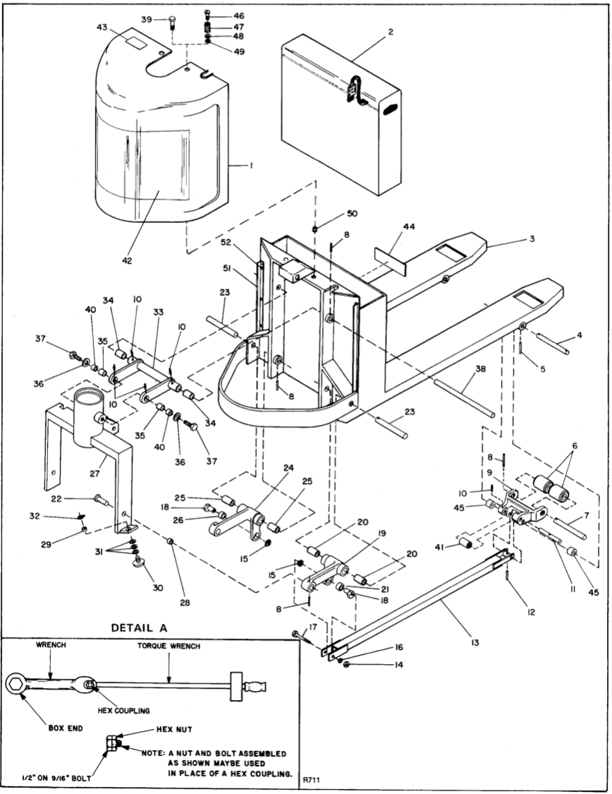
Figure 3-11. Standard Chassis and Pivot Assembly (Eccentric Adjusted Push Rods)
INDEX NO. |
PART NO. |
PART NAME |
NO. REQD. |
INDEX NO. |
PART NO. |
PART NAME |
NO. REQD. |
1 |
----- |
Service Cover (Plastic service cover is no longer available, see paragraph 3-27 for metal cover conversion procedures and kit). |
1 |
|
503429** |
Pivot Arm, Lower Hand, Weldment |
1 |
2 |
003108 |
Battery, 375A, 12 V |
1 |
20 |
053103 |
Bushing |
2 |
|
003109 |
Battery, 450A, 12 V |
1 |
21 |
052939 |
Bushing |
1 |
|
003124 |
Battery, 510A, 12V |
1 |
22 |
503391 |
Spindle |
1 |
3 |
503155 |
Carriage Assy, 27 in. Wide Backrest, 48 in. Fork Length |
1 |
23 |
400458* |
Shaft |
2 |
|
503495 |
Carriage Assy, 27 in. Wide Backrest, 42 in. Fork Length |
1 |
|
296404** |
Shaft (With 025712 Grease Fitting) |
2 |
|
503496 |
Carriage Assy, 27 in. Wide Backrest, 36 in. Fork Length |
1 |
24 |
800167* |
Pivot Arm, Lower Left Hand |
1 |
4 |
294504 |
Shaft, ¾ x 8-5/8 |
1 |
|
503430** |
Pivot Arm, Lower Left Hand |
1 |
5 |
060974 |
Roll Pin, 3/16 x 1-1/4 |
2 |
25 |
053103 |
Bushing |
2 |
6 |
501433 |
Wheel Assembly |
4 |
26 |
052939 |
Bushing |
1 |
|
078255 |
Wheel |
1 |
27 |
501485 |
Yoke (Also 31, fig. 3-5) |
1 |
|
051136 |
Bearing |
2 |
28 |
052923 |
Bushing |
2 |
7 |
312301 |
Axle |
2 |
29 |
052926 |
Bushing |
2 |
8 |
060976 |
Roll Pin, 3/16 x 1-1/2 |
7 |
30 |
501507 |
Saucer Assy |
2 |
9 |
800081 |
Wheel Housing |
2 |
31 |
077026 |
Flat Washer, ¾ |
6 |
10 |
025712 |
Grease Fitting |
6 |
32 |
061719 |
Snap Ring |
2 |
11 |
294505 |
Shaft |
2 |
33 |
800078* |
Pivot Arm Upper (Casting w/o Bushings) |
1 |
12 |
060972 |
Roll Pin, 1/8 x 1 |
2 |
|
501432** |
Pivot Arm Upper (Weldment with Bushings) |
1 |
13 |
503289* |
Push Rod, 36 in. Fork (8 in. Battery Box) |
2 |
34 |
053103 |
Bushing |
2 |
|
503288* |
Push Rod, 42 in. Fork (8 in. Battery Box) |
2 |
35 |
052923 |
Bushing |
2 |
|
503214* |
Push Rod, 48 in. Fork (8 in. Battery Box) |
2 |
36 |
077082 |
Flat Washer, 13/16 I.D. x 1-1/2 O.D. x 9 Ga. |
2 |
|
501422** |
Push Rod, 36 in. Fork (7-1/4 in.) |
2 |
37 |
063869 |
Hex Head Cap Screw, ¾-10 x 2 |
2 |
|
501421** |
Push Rod, 42 in. Fork (7-1/4 in.) |
2 |
38 |
296403 |
Shaft, 1 in. dia x 15-1/2 |
1 |
|
501420** |
Push Rod, 48 in. Fork (7-1/4 in.) |
2 |
39 |
070476†† |
Round Head Screw, ¼-20 x ½ |
2 |
14 |
059437 |
Hex Nut, ½ x 13 |
2 |
40 |
277607 |
Steel Bushing |
2 |
15 |
077412 |
Lock Washer, ½ External Tooth |
2 |
41 |
313301 |
Roller |
2 |
16 |
077213 |
Lock Washer, ½, Split |
2 |
42 |
056475 |
Decal |
1 |
17 |
064710 |
Hex Hd. Cap Screw, ½-13 x 3 |
2 |
43 |
056475 |
Maintenance Decal |
1 |
18 |
400669 |
Eccentric Bushing |
2 |
44 |
056499 |
No-Riding Decal |
1 |
19 |
800168* |
Pivot Arm, Lower Right Hand, Cast |
1 |
45 |
401043† |
Exit Roller |
3 |
Note: For special length Push rods refer to Figure 3-16 for information on how to order replacement parts. |
46 |
057182** |
Stud (Plastic Service Cover) |
2 |
|||
†Standard on trucks serial number 82242 and higher. Older trucks may be retrofitted |
47 |
057176** |
Spring (Plastic Service Cover) |
2 |
|||
*Used on trucks serial number 74870 through 83306. |
48 |
057177** |
Nylon Wear Bushing (Plastic Service Cover) |
2 |
|||
**Used on trucks serial number 74869 and lower. |
49 |
057178** |
Retainer (Plastic Service Cover) |
2 |
|||
††Used with plastic service cover only (See paragraph 3-27 for metal cover attaching hardware). |
50 |
057181** |
Threaded Receptacle (Plastic Service Cover) |
2 |
|||
|
51 |
250736** |
Trim (Plastic Service Cover) |
2 |
|||
52 |
071379** |
Screw (Plastic Service Cover) |
6 |
||||
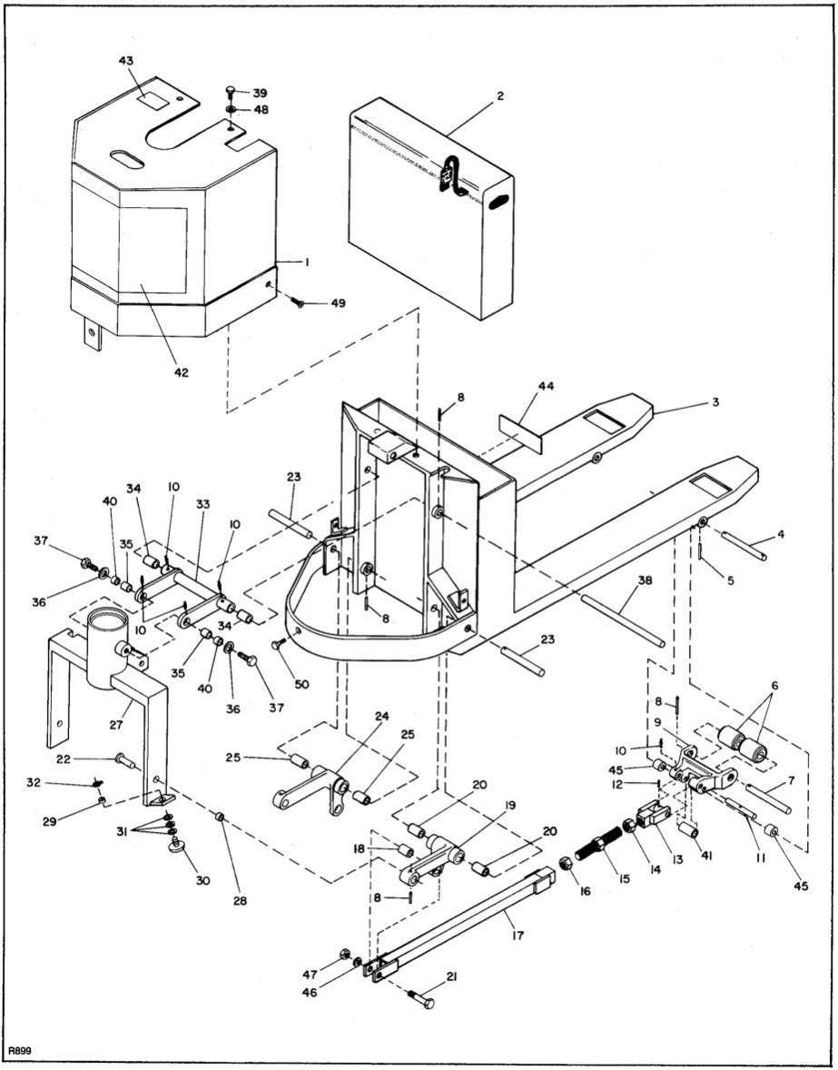
Figure 3-12. Standard Chassis and Pivot Assembly (Universal Push Rods)
INDEX NO. |
PART NO. |
PART NAME |
NO. REQD. |
INDEX NO. |
PART NO. |
PART NAME |
NO. REQD. |
1 |
503731 |
Metal Service Cover |
1 |
19 |
800168 |
Pivot Arm, Lower Right Hand Cast |
1 |
2 |
--- |
Battery (See 2, fig. 3-11) |
1 |
20 |
053103 |
Bushing |
2 |
3 |
503155 |
Carriage Assy, 27 in. Wide Backrest, 48 in. Fork Length |
1 |
21 |
064714 |
Hex Head Screw, ½-13 x 3 |
2 |
|
503495 |
Carriage Assy, 27 in. Wide Backrest, 42 in. Fork Length |
1 |
22 |
503391 |
Spindle |
1 |
|
503496 |
Carriage Assy, 27 in. Wide Backrest, 36 in. Fork Length |
1 |
23 |
400458 |
Shaft |
2 |
4 |
294504 |
Shaft, ¾ x 8-5/8 |
1 |
24 |
800167 |
Pivot Arm, Lower Left Hand |
1 |
5 |
061025 |
Roll Pin, 5/16 x 1 |
2 |
25 |
053103 |
Bushing |
2 |
6 |
501433 |
Wheel Assembly |
4 |
26 |
052939 |
Bushing |
1 |
|
078255 |
Wheel |
1 |
27 |
501485 |
Yoke (Also 31, fig. 3-5) |
1 |
|
051136 |
Bearing |
2 |
28 |
052923 |
Bushing |
2 |
7 |
312301 |
Axle |
2 |
29 |
052926 |
Bushing |
2 |
8 |
060976 |
Roll Pin, 3/16 x 1-1/2 |
7 |
30 |
501507 |
Saucer Assy |
2 |
9 |
800081 |
Wheel Housing |
2 |
31 |
077026 |
Flat Washer, ¾ |
6 |
10 |
025712 |
Grease Fitting |
6 |
32 |
061719 |
Snap Ring |
2 |
11 |
294505 |
Shaft |
2 |
33 |
800078 |
Pivot Arm Upper (Casting w/o Bushings) |
1 |
12 |
060972 |
Roll Pin, 1/8 x 1 |
2 |
34 |
053103 |
Bushing |
2 |
|
900697 |
Universal Push Rod Kit (48-in. straddles) |
2 |
35 |
052923 |
Bushing |
2 |
|
900698 |
Universal Push Rod Kit (42-in. straddles) |
2 |
36 |
077082 |
Flat Washer, 13/16 I.D. x 1-1/2 O.D. x 9 Ga. |
2 |
|
900699 |
Universal Push Rod Kit (36-in. straddles) |
2 |
37 |
063869 |
Hex Head Cap Screw ¾-10 x 2 |
2 |
13 |
503720 |
Cross Head |
1 |
38 |
296403 |
Shaft, 1 in. dia x 15-1/2 |
1 |
14 |
401080 |
Left Hand Hex Jam Nut, 1-8 UNC |
1 |
39 |
063555 |
Hex Head Screw, 5/16-18 x 1 |
2 |
15 |
401078 |
Threaded Stud |
1 |
40 |
277607 |
Steel Bushing |
2 |
16 |
401079 |
Right Hand Hex Jam Nut, 1-8 UNC |
1 |
41 |
313301 |
Roller |
2 |
17 |
503719 |
Push Rod (48 in. straddles) |
1 |
42 |
056475 |
Decal 0566631 door decal |
1 |
|
503732 |
Push Rod (42 in. straddles) |
1 |
43 |
056564 |
Maintenance Decal caution |
1 |
|
503733 |
Push Rod (36 in. straddles) |
1 |
44 |
056499 |
No-Riding Decal |
1 |
18 |
401101 |
Bushing |
1 |
45 |
401043 |
Exit Roller |
4 |
|
|
|
|
46 |
077217 |
Split Lock Washer, ½ |
2 |
|
|
|
|
47 |
059437 |
Hex Nut, ½-13 |
2 |
|
|
|
|
48 |
077210 |
Lock Washer, 5/16 |
2 |
|
|
|
|
49 |
069705 |
Flat Head Screw, ½-13 x 1 |
2 |
|
|
|
|
50 |
063705 |
Hex Head Screw, ½-13 x 1 |
1 |
|
|
|
|
|
900928 |
Decal kit |
|
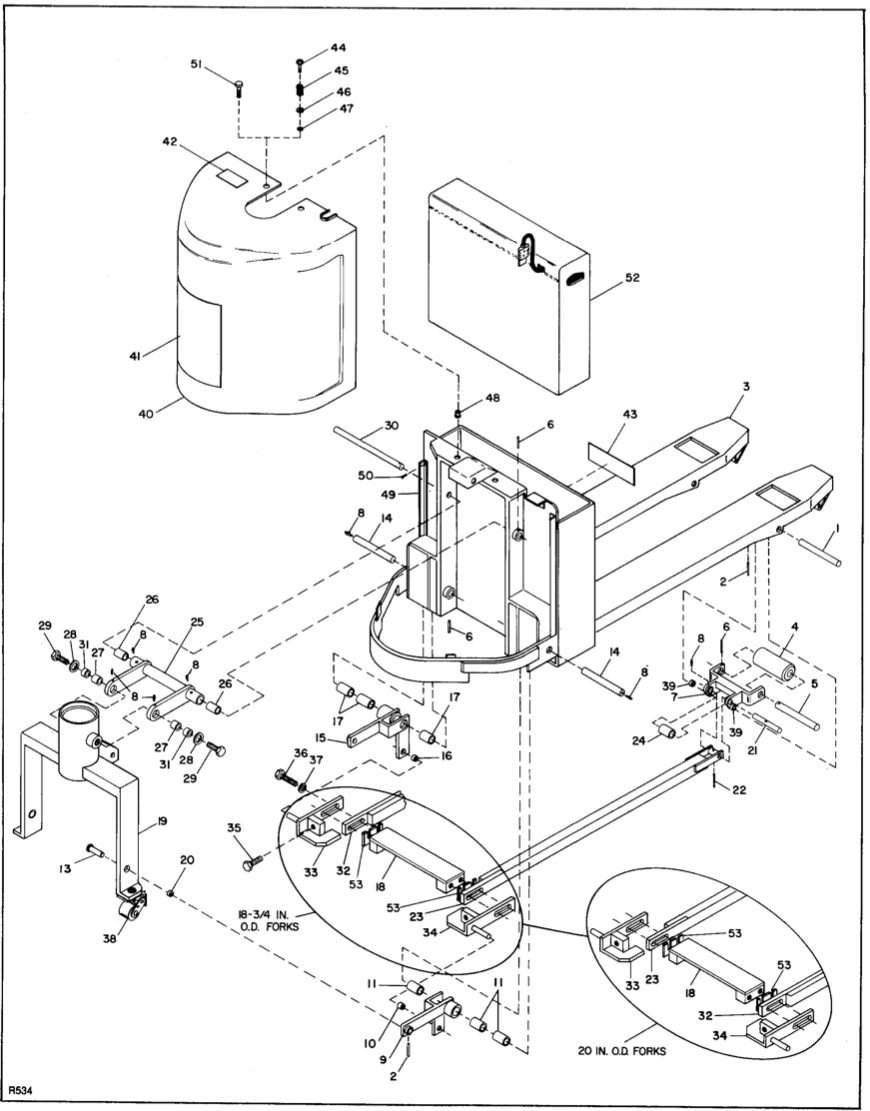
Figure 3-13. Narrow Straddle Chassis & Pivot Assembly
INDEX NO. |
PART NO. |
PART NAME |
NO. REQD. |
INDEX NO. |
PART NO. |
PART NAME |
NO. REQD. |
1 |
294510 |
Shaft |
2 |
25 |
800078* |
Upper Pivot Arm (Cast New Style w/o Bushings) |
1 |
2 |
060974 |
Roll Pin, 3/16 dia x 1-1/4 |
2 |
|
501432** |
Upper Pivot Arm (Weldment Old Style with Bushings) |
1 |
3 |
503582 |
Carriage Assembly, 27 in. Wide Backrest, 18-3/4 Fork O.D. |
1 |
26 |
053103 |
Bushing |
2 |
4 |
501692 |
Wheel Assembly |
2 |
27 |
052923 |
Bushing |
2 |
|
078257 |
Wheel |
1 |
28 |
077082 |
Flat Washer, 13/16 I.D. x 1-1/2 O.D. x 9 Ga. |
2 |
|
051136 |
Bearing |
2 |
29 |
063869 |
Hex Hd Cap Screw, ¾-10 x 2 |
1 |
5 |
312304 |
Axle |
2 |
30 |
296403 |
Shaft |
1 |
6 |
060976 |
RollPin, 3/16 dia. X 1-1/2 |
7 |
31 |
277607 |
Bushing, Steel |
2 |
7 |
800195 |
Wheel Housing (Cast, New Style) |
2 |
32 |
503625* |
Push Rod, Left Hand, 36 in. Forks (8 in. Battery Box) (18-3/4 in straddle) |
1 |
|
501924 |
Wheel Housing (Weldment, Old Style) |
2 |
|
503623* |
Push Rod, Left Hand, 42 in. Forks (8 in. Battery Box) (18-3/4 in straddle) |
1 |
8 |
025712 |
Grease Fitting |
10 |
|
503588* |
Push Rod, Left Hand, 48 in. Forks (8 in. Battery Box) (18-3/4 in straddle) |
1 |
9 |
800194 |
Pivot Arm Lower Right Hand (Cast, New Style) |
1 |
|
503629** |
Push Rod, Left Hand, 36 in. Forks (7-1/4 in. Battery Box) (18-3/4 in. straddle) |
1 |
|
502508** |
Pivot Arm Lower Right Hand (Weldment, Old Style) |
1 |
|
503627** |
Push Rod, Left Hand, 42 in. Forks (7-1/4 in. Battery Box) (18-3/4 in. straddle) |
1 |
10 |
052939* |
Bushing (Used with Pivot Arm P/N 800194) |
1 |
|
501927** |
Push Rod, Left Hand, 48 in. Forks (7-1/4 in. Battery Box) (18-3/4 in. straddle) |
1 |
|
052923** |
Bushing (Used with Pivot Arm P/N 502508) |
1 |
|
503630 |
Push Rod, Left Hand, 36 in. Forks (7-1/4 in. Battery Box) (20 in. straddle) |
1 |
11 |
052929** |
Bushing (Used with Pivot Arm P/N 502508) |
3 |
|
503628 |
Push Rod, Left Hand, 42 in. Forks (7-1/4 in. Battery Box) (20 in. straddle) |
1 |
12 |
052923 |
Bushing |
A/R |
|
503926 |
Push Rod, Left Hand, 48 in. Forks (7-1/4 in. Battery Box) (20 in. straddle) |
1 |
13 |
503391 |
Spindle |
2 |
33 |
502116 |
Lug Weldment, Left Hand |
1 |
14 |
296409 |
Shaft |
2 |
34 |
502115 |
Lug Weldment, Right Hand |
1 |
15 |
800193* |
Pivot Arm, Lower Left Hand (Cast, New Style) |
1 |
35 |
065620 |
Hex Head Cap Screw, ¾ x 2 |
2 |
|
502509** |
Pivot Arm, Lower Left Side (Weldment and Bushings) |
1 |
36 |
063870 |
Hex Head Cap Screw, ¾ x 2-1/2 |
4 |
16 |
052939** |
Bushing (Used with P/N 502509) |
1 |
37 |
077217 |
Lock Washer, ¾ |
4 |
|
052923 |
Bushing (Used with P/N 502509) |
1 |
38 |
502331 |
Caster Assembly (See fig. 3-11) |
REF |
17 |
052929 |
Bushing |
3 |
39 |
313307 |
Spacer |
2 |
18 |
501928 |
Push Rod Yoke |
1 |
40 |
--- |
Service Cover (Plastic Service Cover is no longer available, see paragraph 3-27 for conversion procedures and kit). |
1 |
19 |
502502 |
Yoke (Also 31, fig. 3-5) |
1 |
41 |
056475 |
Decal |
1 |
20 |
052939 |
Bushing |
2 |
42 |
056564 |
Maintenance Decal |
1 |
21 |
294510 |
Shaft |
2 |
43 |
056499 |
No Riding Decal |
1 |
22 |
060972 |
Roll Pin, 3/16 dia x 1 in. |
2 |
44 |
057182** |
Stud (Plastic Service Cover) |
2 |
23 |
503626* |
Push Rod, Right Hand, 36 in. Forks (8 in. Battery Box) (18-3/4 in. straddle) |
1 |
45 |
057176** |
Spring (Plastic Service Cover) |
2 |
|
503624* |
Push Rod, Right Hand, 42 in. Forks (8 in. Battery Box) (18-3/4 in. straddle) |
1 |
46 |
057177** |
Nylon Wear Bushing (Plastic Service Cover) |
2 |
|
503589* |
Push Rod, Right Hand, 48 in. Forks (8 in. Battery Box) (18-3/4 in. straddle) |
1 |
47 |
057178** |
Retainer (Plastic Service Cover) |
2 |
|
503630** |
Push Rod, Right Hand, 36 in. Forks (7-1/4 in. Battery Box) (18-3/4 in. straddle) |
1 |
48 |
057181** |
Threaded Receptacle (Plastic Service Cover) |
2 |
|
503628** |
Push Rod, Right Hand, 42 in. Forks (7-1/4 in. Battery Box) (18-3/4 in. straddle) |
1 |
49 |
250736** |
Trim (Plastic Service Cover) |
2 |
|
501926** |
Push Rod, Right Hand, 48 in. Forks (7-1/4 in. Battery Box) (18-3/4 in. straddle) |
1 |
50 |
071379** |
Screw (Plastic Service Cover) |
6 |
|
503629 |
Push Rod, Right Hand, 36 in. Forks (7-1/4 in. Battery Box) (20 in. straddle) |
1 |
51 |
---†† |
Round Head, ¼-20 x 1/7 |
2 |
|
503627 |
Push Rod, Right Hand, 42 in. Forks (7-1/4 in. Battery Box) (20 in. straddle) |
1 |
52 |
--- |
Battery (See 2, fig. 3-11) |
1 |
|
503927 |
Push Rod, Right Hand, 48 in. Forks (7-1/4 in. Battery Box) (20 in. straddle) |
1 |
53 |
400612 |
Spacer |
A/R |
24 |
313301 |
Exit Roller |
2 |
|
|||
††Used with plastic service cover. (See paragraph 3-27 for metal cover attaching hardware. | |||||||
Note: For special length Pushrods, refer to Fig. 3-16 for information on ordering replacement parts. | |||||||
*Used on trucks serial number 74870 and higher. | |||||||
**Used on trucks serial number 74869 and lower. | |||||||
|
3-16. WHEEL HOUSINGS AND EXIT ROLLERS
|
1.Refer to figure 3-14, and cut pivot blocks from both straddles with a torch then clean off slag to assure proper fit of new parts. 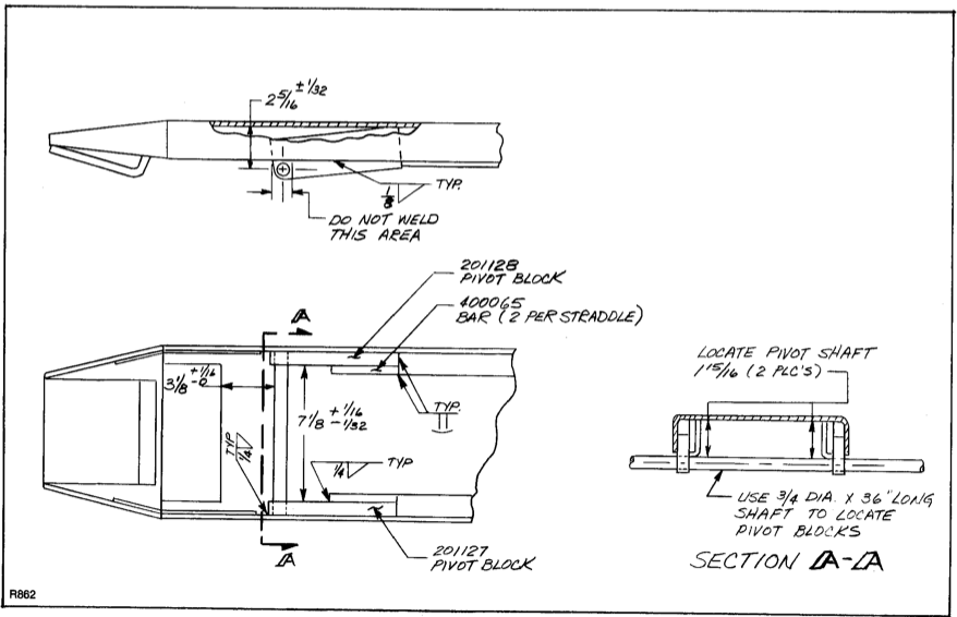 Figure 3-14. Straddle and Pivot Blocks |
c. Modifying and Installing Wheel Housing. |
3-17. SAUCER ASSEMBLY AND CASTER REPLACEMENT. 1. Disconnect battery. 2. Securely block the load wheels to prevent the truck from moving. 3. Remove service cover. 4. Use a jack to raise the rear of the lift truck so that the drive wheel clears the ground. 5. Lower the truck on blocks, making certain the drive wheel os still clear of the ground. 6. Refer to the figure 3-11 or 3-12 as a guide in replacing the saucer assemblies (of standard-chassis trucks) when required. 7. Refer to figure 3-13 as a guide in replacing the casters (of narrow-straddle trucks) when required. NOTE: The caster assembly illustrated in figure 3-17 is interchangeable with the older style caster assembly which is no longer available. If you are replacing an older style caster, it is recommended that both casters be replaced. |
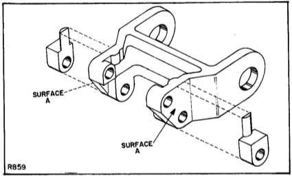
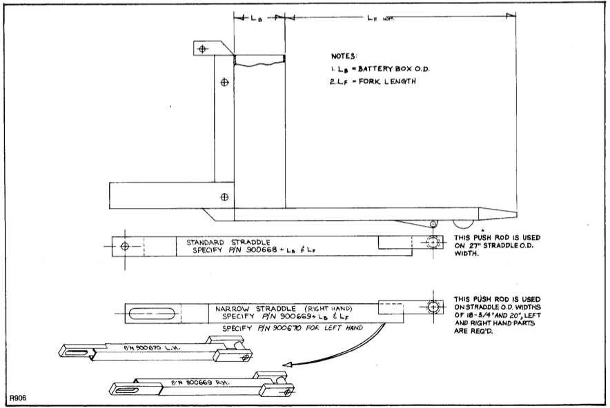
Figure 3-16. Special Length Push Rods.
|
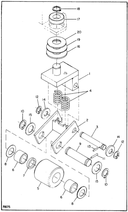 Figure 3-17. Caster Assembly
d |
3-18. LOAD WHEEL REPLACEMENT. The standard wheel assembly is illustrated in figures 3-11 and 3-12) and the tandem wheel assembly is illustrated in figure 3-18. 1. Disconnect battery. 2. Block the drive wheel to prevent the truck from moving. 3. Place a hydraulic jack under each straddle at reinforced section behind the load wheel under the pushrod. Raise the straddles until the load wheels clear the floor. 4. REmove roll pin securing wheel housing pivot shaft and pull shaft out of straddle. 5. Refer to exploded views to disassemble the wheel assembly. 3-19. Transmission Repair. (Figure 3-19) To remove and disassemble the transmission (complete with drive wheel) proceed as follows: 1. Disconnect battery. 2. Securely block load wheels. REmove service cover. 3. Label all wire and cable leads connected to terminals mounted on the transmission; then disconnect the leads. 4. MAke sure the four cables to the drive motor are properly labeled A1, A2, F1, and F2; then disconnect the cables from the drive motor. 5. Disconnect the mechanical brake by removing clevis pin that secures the rod clevis to the lower level assembly. 6. Remove the drain plug (12) and drain the transmission oil. 7. Remove the two screws (39) and lock washers (29) which secure the motor to the transmission housing. LAy motor and attached brake parts aside until reassembly. 8. Disconnect brake rod from lower lever assembly. 9. Remove the four screws and washers that secure the transmission to the pivot tube assembly. 10. Remove the transmission and drive wheel from the truck by raising the rear of the lift truck with jacks or other suitable means and sliding the assembly out from under the truck. 11. Remove the four hex head cap screws (35) and lock washers (34), bearing cap (33) and gasket (32). 12. Remove bearing spacer (26). |
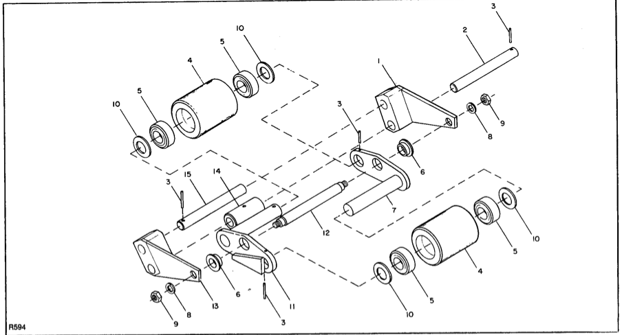
Figure 3-18. Tandem Load Wheels
INDEX NO. |
PART NO. |
PART NAME |
NO. REQD. |
INDEX NO. |
PART NO. |
PART NAME |
NO. REQD. |
|
501691 |
Tandem Load Wheels |
2 |
8 |
077213 |
Lock Washer, ½ |
2 |
1 |
502592 |
Lift Arm, L.H. |
1 |
9 |
059537 |
Jam Nut, ½-13 |
2 |
2 |
294504 |
Shaft |
1 |
10 |
077033 |
Flat Washer, 1-inch |
4 |
3 |
060976 |
Roll Pin |
4 |
11 |
501813 |
Stop Block |
1 |
|
501692 |
Load Wheel Assy |
2 |
12 |
240634 |
Shaft |
1 |
4 |
078257 |
Wheel (Poly) |
1 |
13 |
502593 |
Lift Arm, R.H. |
1 |
5 |
051136 |
Ball Bearing |
2 |
14 |
400697 |
Spacer |
1 |
6 |
800157 |
Bushing |
2 |
15 |
294508 |
Shaft |
1 |
7 |
501690 |
Side Plate with Axle |
1 |
|
|
|
|
|
13. Remove seven screws (30), two screws (38), and their lock washers (29); pry off transmission cover (28) and pull off cover gasket (27). 14. Remove ball bearing (25) and pinion spacer (24). 15. Remove intermediate gear (23) and square key (22). 16. Remove spur pinion (21). 17. Remove locknut (15) and lock washer (14). 18. Remove drive wheel and axle shaft (6) to free gear (13), roller bearing cones (8) and cups (9), and oil seal (7). 19. Remove ball bearing (20). 20. Refer to the disassembly instructions as a guide, and reverse the individual procedures of steps 19 through 1 to reassemble and reinstall the transmission. 21. Fill with transmission oil to fill plug. |
3-20. DRIVE WHEEL REPLACEMENT. 1. Disconnect battery. 2. Securely block the load wheels to prevent the truck from moving. 3. Remove service cover. 4. Use a jack to raise the rear of the lift truck so that the drive wheel clears the ground. 5. Lower the truck on blocks, making certain the drive wheel is still clear of the grpound. 6. Remove the five retaining screws and lock washers that secure the drive wheel to the axle shaft and then pry off the wheel. 7. Reverse the above procedure to install new drive wheel. |
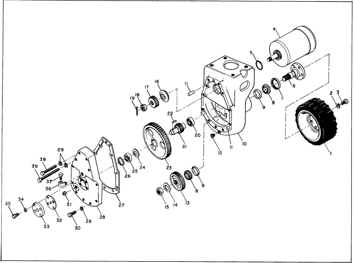
Figure 3-19. Transmission and Drive Wheel
INDEX NO. |
PART NO. |
PART NAME |
NO. REQD. |
INDEX NO. |
PART NO. |
PART NAME |
NO. REQD. |
1 |
501600 |
Drive Wheel, Rubber Lug |
1 |
21 |
057211 |
Spur Pinion |
1 |
2 |
077215 |
Lock Washer, 5/8 |
5 |
22 |
057902 |
Square Key, 5/16 x 1-3/8 |
1 |
3 |
064828 |
Hex Hd Cap Screw |
5 |
23 |
057233 |
Intermediate Gear |
1 |
4 |
016020 |
Drive Motor (See fig. 3-9) |
1 |
24 |
074701 |
Pinion Spacer |
1 |
|
501596 |
Transmission Assy |
1 |
25 |
051125 |
Bearing |
1 |
5 |
042114 |
O-ring |
1 |
26 |
074706 |
Bearing Spacer |
1 |
6 |
050700 |
Axle Shaft |
1 |
27 |
036105 |
Cover Gasket |
1 |
7 |
073504 |
Oil Seal |
1 |
28 |
800073 |
Transmission Cover |
1 |
8 |
051112 |
Roller Bearing Cone |
2 |
29 |
077211 |
Lock Washer, 3/8 |
11 |
9 |
051111 |
Roller Bearing Cup |
2 |
30 |
064611 |
Hex Hd Cap Screw, 3/8-16 x 1-3/4 |
7 |
10 |
800072 |
Housing |
1 |
31 |
026304 |
Fill Plug, 3/8 Pipe Thread |
1 |
11 |
060585 |
Dowel Pin |
3 |
32 |
036106 |
Bearing Cap Gasket |
1 |
12 |
026302 |
Drain Plug |
1 |
33 |
051159 |
Bearing Cap |
1 |
13 |
057210 |
Gear |
1 |
34 |
077210 |
Lock Washer, 5/16 |
4 |
14 |
077600 |
Lock Washer |
1 |
35 |
063555 |
Hex Hd Cap Screw, 5/16-18 x 1 |
4 |
15 |
059680 |
Locknut |
1 |
36 |
026704 |
Street Elbow |
1 |
16 |
074702 |
Motor Pinion Spacer |
1 |
37 |
076701 |
Vent |
1 |
17 |
057234 |
Motor Pinion Spur |
1 |
38 |
064615 |
Hex Hd Cap Screw, 3/8-16 x 2-1/4 |
2 |
18 |
059745 |
Hex Nut, 5/8-18 |
1 |
39 |
064620 |
Hex Hd Cap Screw, 3/8-16 x 3-3/4 |
2 |
19 |
060428 |
Cotter Pin |
1 |
|
|||
20 |
051126 |
Ball Bearing |
1 |
||||
|
3-21. HYDRAULIC SYSTEM REPAIR (FIGURE 3-20 OR 3-21) Figure 3-20 illustrates the complete hydraulic systems for trucks with serial number 81936 and lower. The hydraulic system for newer trucks is shown in figure 3-21. The pump-motor-reservoir assembly (1) and the lift cylinder are repairable. |
Refer to paragraphs 3-22 and 3-23 for instructions for removing, disassembling, and repairing these assemblies. WARNING: Before disconnecting hydraulic lines, make certain that the system is not under pressure. |
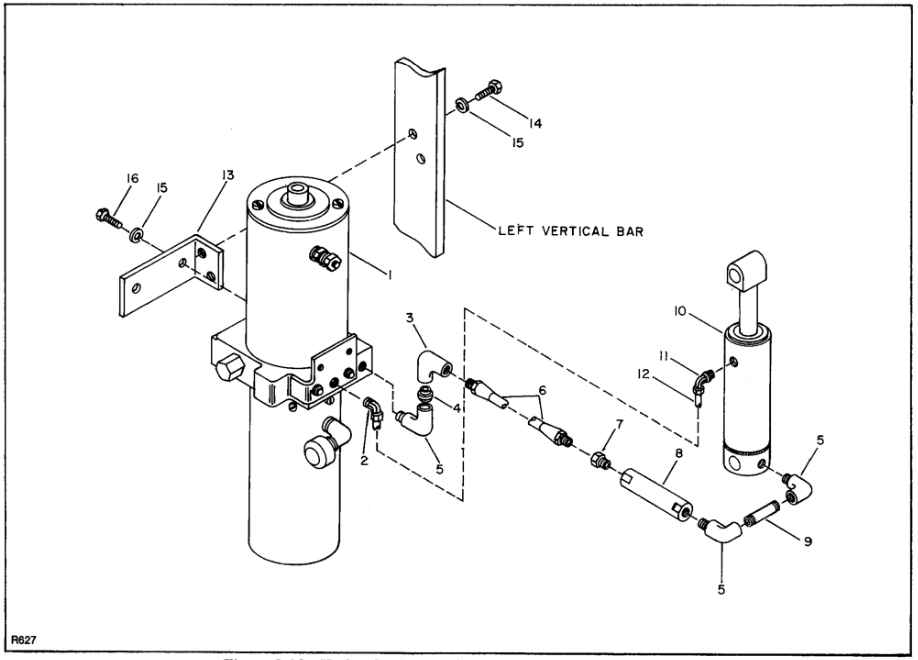
Figure 3-20. Hydraulic System (Serial Number 81936 and Lower)
INDEX NO. |
PART NO. |
PART NAME |
NO. REQD. |
INDEX NO. |
PART NO. |
PART NAME |
NO. REQD. |
1 |
016575 |
Pump-Motor-Reservoir Assy (See fig. 3-22) |
1 |
9 |
026135 |
Nipple |
1 |
2 |
025532 |
90° Adapter |
1 |
10 |
047552 |
Lift Cylinder (See fig. 3-24) |
1 |
3 |
025521 |
Elbow |
1 |
11 |
025501 |
90° Adapter |
1 |
4 |
026110 |
Nipple |
1 |
12 |
282515 |
Vinyl Tube |
1 |
5 |
026708 |
Street Elbow |
3 |
13 |
161295† |
Bracket |
1 |
6 |
501498 |
Hose Assy |
1 |
14 |
064607† |
Hex Hd Cap Screw, 3/8-16 x 1-1/4 |
2 |
7 |
025313 |
Adapter |
1 |
15 |
077211†† |
Lock Washer, 3/8 |
2 |
8 |
047110 |
Flow Regulator |
1 |
16 |
063603 |
Hex Hd Cap Screw, 3/8-16 x 3/4 |
2 |
†Used on trucks serial numbers 74870 to 81937. |
††Four used on trucks serial number 74869 and lower. |
||||||
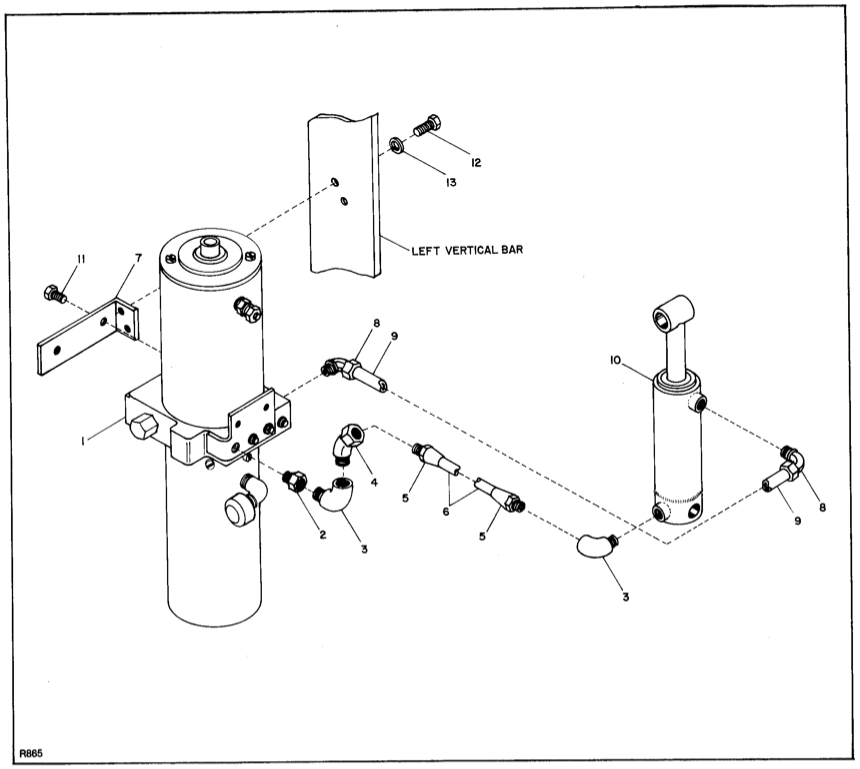
Figure 3-21. Hydraulic System.
(Serial Numbers 81937 and Higher)
INDEX NO. |
PART NO. |
PART NAME |
NO. REQD. |
INDEX NO. |
PART NO. |
PART NAME |
NO. REQD. |
|
016575 |
Pump-Motor-Reservoir Assy (1, fig. 3-20) |
REF |
|
900282 |
Pump Assy with Solenoid Cartridge |
1 |
|
900271 |
Pump Motor |
1 |
12 |
900281 |
Pump Assy |
1 |
1 |
009305 |
Commutator End Head |
1 |
13 |
900272 |
Solenoid Cartridge |
1 |
2 |
003501 |
Brush Spring & Holder Package |
1 |
14 |
900273 |
Solenoid Strainer |
1 |
3 |
003702 |
Brush Set |
1 |
15 |
900276 |
O-ring |
1 |
4 |
900172 |
Thrust Washer |
1 |
16 |
900270 |
Strainer |
1 |
5 |
900171 |
Field Coil Package |
1 |
17 |
900268 |
Reservoir |
1 |
6 |
900170 |
Thru Bolt Package |
1 |
18 |
026704 |
Street Elbow |
1 |
7 |
900173 |
Terminal Stud Package |
1 |
19 |
029102 |
Breather (Supplied with pump) |
1 |
8 |
900280 |
Armature |
1 |
20 |
900279 |
Magnet |
1 |
9 |
051168 |
Drive End Bearing |
1 |
21A |
900266 |
Solenoid Start Switch (Early Models) |
1 |
10 |
900275 |
Coupling |
1 |
21B |
020419 |
Solenoid Start Switch (Late Models) |
1 |
11 |
900274 |
Oil Seal |
1 |
|
|||
|
3-22. HYDRAULIC PUMPUMP-MOTOR-RESERVOIR ASSEMBLY. (Figures 3-22 and 3-23) The hydraulic pump-motor-reservoir assembly may be repaired. The motor can be rebuilt, but a defective pump has to be replaced as complete unit. Refer to figure 3-22 for breakdown of motor. Proceed as follows to remove and disassemble hydraulic pump-motor-reservoir assembly: 1. Lower lift carriage fully and disconnect battery. WARNING: Before disconnecting hydraulic lines, make certain that the system is not under pressure. 2. Remove service cover. 3. Unscrew breather cap and drain the hydraulic oil from the reservoir into a clean bucket or suitable container. |
NOTE: A few feet of ½-inch hose will facilitate draining oil from the reservoir. 4. Remove hydraulic lines from pump and electric wires from motor, labeling each wire to assure proper reassembly. 5. Remove assembly from truck by removing the screws and lock washers that secure it and its mounting bracket to the left vertical bar of the carriage assembly. 6. Disassemble using figure 3-22 as a guide for pump-motor-reservoir assembly 016575 and 3-23 for assembly 016580. NOTE: Before reassembling pump-motor-reservoir assembly, it is recommended that all O-rings and gaskets be replaced. |

Figure 3-22 Pump-Motor-Reservoir Assembly. (Serial Numbers 81936 and Lower)
INDEX NO. |
PART NO. |
PART NAME |
NO. REQD. |
INDEX NO. |
PART NO. |
PART NAME |
NO. REQD. |
|
016575 |
Pump-Motor-Reservoir Assy (1, fig. 3-20) |
REF |
|
900282 |
Pump Assy with Solenoid Cartridge |
1 |
|
900271 |
Pump Motor |
1 |
12 |
900281 |
Pump Assy |
1 |
1 |
009305 |
Commutator End Head |
1 |
13 |
900272 |
Solenoid Cartridge |
1 |
2 |
003501 |
Brush Spring & Holder Package |
1 |
14 |
900273 |
Solenoid Strainer |
1 |
3 |
003702 |
Brush Set |
1 |
15 |
900276 |
O-ring |
1 |
4 |
900172 |
Thrust Washer |
1 |
16 |
900270 |
Strainer |
1 |
5 |
900171 |
Field Coil Package |
1 |
17 |
900268 |
Reservoir |
1 |
6 |
900170 |
Thru Bolt Package |
1 |
18 |
026704 |
Street Elbow |
1 |
7 |
900173 |
Terminal Stud Package |
1 |
19 |
029102 |
Breather (Supplied with pump) |
1 |
8 |
900280 |
Armature |
1 |
20 |
900279 |
Magnet |
1 |
9 |
051168 |
Drive End Bearing |
1 |
21A |
900266 |
Solenoid Start Switch (Early models) |
1 |
10 |
900275 |
Coupling |
1 |
21B |
020419 |
Solenoid Start Switch (Late Models) |
1 |
11 |
900274 |
Oil Seal |
1 |
|
|||
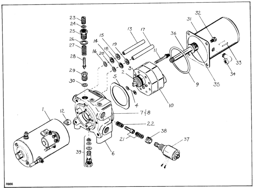
Figure 3-23. Pump-Motor Reservoir Assembly. (Serial Numbers 81937 and Higher)
INDEX NO. |
PART NO. |
PART NAME |
NO. REQD. |
INDEX NO. |
PART NO. |
PART NAME |
NO. REQD. |
|
016580 |
Pump-Motor-Reservoir Assy (1, fig. 3-22) |
1 |
17 |
|
Return Tube |
1 |
1 |
900271 |
Pump-Motor (See fig. 3-22, items 1 through 9) |
REF |
18 |
|
Push On Ring |
1 |
|
900682 |
Pump Seal Kit |
1 |
19 |
|
Washer |
1 |
2 |
|
Oil Seal |
1 |
20 |
|
O-Ring |
1 |
3 |
|
O-Ring |
1 |
|
900688 |
Flow Regulator Kit |
1 |
4 |
|
O-Ring |
2 |
21 |
|
Flow Control Spool |
1 |
5 |
|
Gasket |
1 |
22 |
|
Spring |
1 |
|
900683 |
Adapter Kit |
1 |
|
900692 |
Relief Valve Kit |
1 |
6 |
|
Adapter |
1 |
23 |
|
Adjusting Screw |
1 |
7 |
|
Retainer |
1 |
24 |
|
O-Ring |
1 |
8 |
|
Screw |
2 |
25 |
|
Hex Cap Nut |
1 |
9 |
|
O-Ring |
1 |
26 |
|
Gasket |
1 |
|
900684 |
Pump Kit |
1 |
27 |
|
Spring |
1 |
4 |
|
O-Ring |
1 |
28 |
|
Plunger |
1 |
5 |
|
Gasket |
2 |
29 |
|
Relief Valve Seat |
1 |
10 |
|
Pump |
1 |
30 |
|
O-Ring (Relief Valve Seat) |
1 |
11 |
|
Screw |
4 |
31 |
900693 |
Reservoir |
1 |
12 |
|
Coupling |
1 |
32 |
900694 |
Hex Hd Screw, Thread Forming, ¼-20 x 3/8 |
6 |
|
900685 |
By-Pass Tube Assy |
1 |
33 |
900279 |
Magnet |
1 |
13 |
|
Return Tube |
1 |
34 |
026703 |
Street Elbow |
1 |
14 |
|
Push On Ring |
1 |
35 |
900270 |
Strainer (Reservoir) |
1 |
15 |
|
Shim |
1 |
36 |
026129 |
3/8 Pipe Nipple, 5 in. Long (Inlet) |
1 |
16 |
|
O-Ring |
1 |
37 |
900700 |
12-volt Solenoid Release Valve |
1 |
|
900686 |
Return Tube Assy |
1 |
38 |
900273 |
Solenoid Strainer |
1 |
|
39 |
900695 |
Check Valve Assy |
1 |
|||
|
3-23. LIFT CYLINDER REPAIR Two different lift cylinders are used on the PPT-40. When disassembling lift cylinder, be sure to refer to the correct procedure. The cylinder can easily be identified by the inlet and outlet parts. On lift cylinder P/N 047552 (figure 3-24) the parts are flush with the barrel assembly. On lift cylinder P/N 047654 (figure 3-25) the parts protrude from the barrel assembly. Refer to paragraph 3-23b to disassemble lift cylinder P/N 047552, and to paragraph 3-23c for lift cylinder P/N 047654. a. Removal from Truck. 1. Fully lower the lift carriage. 2. Disconect battery. 3. Remove service cover. WARNING: Before disconnecting any hydraulic lines, make certain the system is not under pressure. 4. Disconnect overflow hose from top of lift cylinder. |
5. Remove snap rings (18). 6. Remove top shaft (16) and bottom shaft (17); then withdraw lift cylinder down and away from the lift carriage. b. Disassembly of Lift Cylinder P/N 047552 (Figure 3-24) 1. Secure lift cylinder in a vise; then remove lock wire (4) and spacer (5). 2. Remove retaining ring (6). 3. Pull out eye (1), withdrawing rod (9), cylinder head (7), and attached parts. CAUTION: Use proper pipe-clamp vise with non-marring jaws to prevent damaging the finish on the rod. 4. Secure rod in vise; then remove retaining ring (13) and packing (12). 5. Remove screw (14), piston (11), and O-ring (10). 6. Loosen nut (2) and remove it and eye (1) from rod (9). |
Figure 3-24. Lift Cylinder P/N 047552
INDEX NO. |
PART NO. |
PART NAME |
NO. REQD. |
INDEX NO. |
PART NO. |
PART NAME |
NO. REQD. |
|
047552 |
Lift Cylinder (10, fig. 3-13) |
REF |
10 |
900256* |
Rod O-ring |
1 |
1 |
900264 |
Eye |
1 |
11 |
900255 |
Piston |
1 |
2 |
900263 |
Jam Nut, ¾-10 |
1 |
12 |
900254* |
Packing |
1 |
3 |
900262* |
Wiper |
1 |
13 |
900253* |
Packing Retaining Ring |
1 |
4 |
900265* |
Lock Wire |
1 |
14 |
900252 |
Hex Head Cap Screw |
1 |
5 |
900261* |
Spacer |
1 |
15 |
900251 |
Barrel Assembly |
1 |
6 |
900260* |
Head Retaining Ring |
1 |
16 |
294519 |
Shaft |
2 |
7 |
900258 |
Head |
1 |
17 |
061719 |
Snap Ring |
4 |
8 |
900259* |
Head O-ring |
1 |
*Included in 900547 repacking kit. |
|||
9 |
900257 |
Rod |
1 |
||||
|
7. Withdraw cylinder head (7) from rod. 8. Remove O-ring (8) and wiper (3). NOTE: Before reassembling the hydraulic lift cylinder, it is recommended that the O-rings (8, 10) and packing (12) be replaced. c. Disassembly of Lift Cylinder P/N 047564 (Figure 3-25) 1. Secure lift cylinder barrel in a vise. |
2. Locate hole in side of lift cylinder where lock wire (6) is visible. 3. Rotate gland (5) clockwise and lock wire (6) should exit through hole. Remove lock wire. 4. Pull up on eye (1) to extract rod (8) piston (10) and attching parts from barrel (15). CAUTION: Use proper pipe clamp vise with non-maring jaws to prevent damaging the finish of the rod. |
Figure 3-25. Lift Cylinder P/N 047564
INDEX NO. |
PART NO. |
PART NAME |
NO. REQD. |
INDEX NO. |
PART NO. |
PART NAME |
NO. REQD. |
|
047564 |
Lift Cylinder |
REF |
10 |
900681 |
Piston |
1 |
1 |
900576 |
Eye |
1 |
11 |
900674* |
O-ring Piston |
1 |
2 |
900577 |
Jam Nut, ¾-10 |
1 |
12 |
900675* |
Piston Seal |
1 |
3 |
900578* |
Wiper |
1 |
13 |
900676* |
Wear Strip |
1 |
4 |
900579* |
Seal |
1 |
14 |
900587 |
Hex Nut, Self Locking |
1 |
5 |
900680 |
Gland |
1 |
15 |
900678 |
Barrel Assembly |
1 |
6 |
900677* |
Lock Wire |
1 |
16 |
294519 |
Shaft |
2 |
7 |
900672* |
Gland Static |
1 |
17 |
061719 |
Snap Ring |
4 |
8 |
900679 |
Rod |
1 |
*Part of cylinder rebuilding kit P/N 900671 |
|||
9 |
900673* |
Rod Static Seal |
1 |
||||
|
5. Secure rod in vise; then remove nut (14), piston (10) and rod static seal (9). 6. Remove nut (2) and eye (1) from rod (8). 7. Withdraw gland (5) from rod. NOTE: Use parts in rebuilding kitP/N 900671 to replace items 3, 4, 6, 7, 9, 11, 12 and 13 before reassembly. 8. Reassemble in reverse order of disassembly. Insert lock wire (6) through slot in side of barrel and rotate gland (5) counterclockwise until lock wire is wrapped into barrel to lock assembly together. 3-24. Contactor Tip Replacement. (Figure 3-26 through 3-29) The contactor tips (forward and reverse) should be replaced if they are badly pitted or worn. It is advisable to replace the movable and stationary contact tips at the same time. (Refer to Figure 3-27 part number identification of replacement parts). Proceed as follows: 1. Disconnect battery. 2. If they are not clearly marked, label the wires connected to the contactor tips (see figure 3-26). 3. Refer to figure 3-27. Replace the movable contactor tips and reinstall hardware and insulators as illustrated. (Kit No. 900140 is available for replacement hardware.) 4. Remove hex head screws that secure wires, jumpers, and stationary contacts. Replace stationary contacts |
and reinstall jumpers. Refer to figure 3-26 to reconnect wires. Reinstall screws. 5. Check that contact gap is at least 3/16 inch at contact tip center. 6. Connect battery. 3-25. Speed Control Resistor Adjustment. (Figures 3-28 and 3-30) Each half of the speed control resistor is switched in series with the drive motor and the negative side of the battery during one or more steps of acceleration. Moving the terminals on the speed control resistor changes the resistance in the circuit, which changes the rate of travel of the truck in foirst and second speed. NOTE: The speed control resistor is adjusted at the factory for a reasonable set of speed increments. Do not alter the setting without a good reason. 1. Referring to the schematic diagram, locate the end terminal that supplies current to the speed control resistor in first speed. 2. Move this terminal awayfrom the center terminal, lengthening the effective resistance strip, to decrease the rate of travel in first speed. 3. Move both the terminals away from the center terminal to decrease the rate of travel in first and second speeds. |
Figure 3-26. 70-Amp Contactor Wire Terminations
Figure 3-27. 70-Amp Contactor Tip Replacement
INDEX NO. |
PART NO. |
PART NAME |
NO. REQD. |
|
005604 |
Contactor Assembly 70-Amp (12V) |
1 |
1 |
005610 |
Contactor Bar Assy L.H. |
1 |
2 |
005609 |
Contactor Bar Assy R.H. |
1 |
|
900140 |
Plunger Tip Assy |
1 |
3 |
NP |
Nut |
1 |
4 |
NP |
Lock Washer |
1 |
5 |
NP |
Flat Washer |
1 |
6 |
NP |
Insulator |
1 |
7 |
NP |
Insulator |
1 |
8 |
NP |
Spring |
1 |
9 |
005113 |
Coil (12V) |
1 |
10 |
017821 |
Plunger |
1 |
11 |
062921 |
Hex Screw ¼-20 x ½ |
4 |
12 |
077219 |
Lock Washer, ¼ |
4 |
13 |
005608 |
Stationary Contact Tip |
4 |
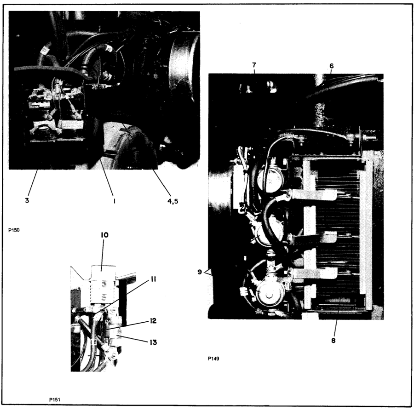
Figure 3-28. Electrical Control Components and Battery Connector Group (Serial Number 67146 to 70874)
INDEX NO. |
PART NO. |
PART NAME |
NO. REQD. |
INDEX NO. |
PART NO. |
PART NAME |
NO. REQD. |
|
502382 |
Contactor Panel Assy |
1 |
9 |
020419 |
Solenoid |
2 |
1 |
502358 |
Enclosure |
1 |
|
501607 |
Battery Connector Group |
1 |
2 |
250743 |
Cover (not shown) |
1 |
10 |
005410 |
Battery Connector |
1 |
3 |
005604 |
Contactor Assy |
1 |
11 |
800069 |
Fuse Block (one stud) |
1 |
4 |
008904 |
Fuse Receptacle |
1 |
12 |
008902 |
Fuse Block (two studs) |
1 |
5 |
008910 |
Fuse, 15-A |
1 |
13 |
008906 |
Fuse, 300-A |
1 |
|
502370 |
Resistor Assy |
1 |
14 |
012707 |
Time Delay Relay, One Second (optional) (not shown) |
1 |
6 |
018907 |
Dynamic Brake Resistor |
1 |
15 |
021708 |
Time Delay Relay, Two Second (optional) (not shown) |
1 |
7 |
020719 |
Dynamic Brake Solenoid |
1 |
|
|||
8 |
018900 |
Speed Control Resistor |
1 |
||||
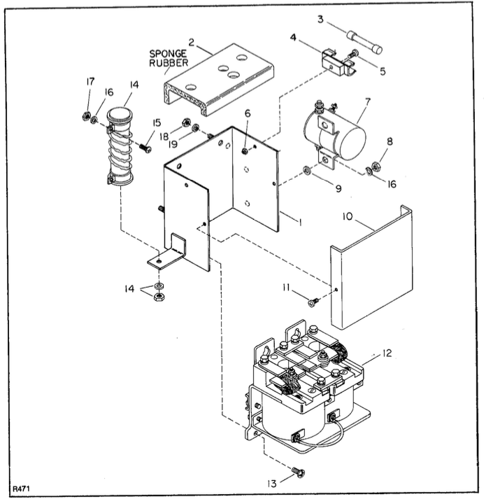
Figure 3-29. Contactor Panel (Serial Number 70875 and Higher)
INDEX NO. |
PART NO. |
PART NAME |
NO. REQD. |
|
502382 |
Contactor Panel Assy |
1 |
1 |
502358 |
Enclosure |
1 |
2 |
306201 |
Dust Cover |
1 |
3 |
008910 |
Fuse, 15-Amp |
1 |
4 |
008904 |
Fuse Block |
1 |
5 |
068230 |
Round Hd Screw, 6-32 x 3/8 |
1 |
6 |
059412 |
Hex Nut, 6-32 |
1 |
7 |
020719 |
Dynamic Brake Solenoid |
1 |
8 |
059416 |
Hex Nut, ¼-20 |
2 |
9 |
077011 |
Washer, 5/15 |
2 |
10 |
250743 |
Cover |
1 |
11 |
071379 |
Screw |
2 |
12 |
005604 |
Contactor Assy |
1 |
13 |
071379 |
Screw |
4 |
14 |
018907 |
Dynamic Brake Resistor, with Mounting Hardware |
1 |
15 |
068407 |
Lock Washer, No. 10 |
2 |
16 |
077208 |
Hex Nut, 10-32 |
4 |
17 |
059416 |
Hex Nut, ¼-32 |
2 |
18 |
059421 |
Hex Nut, ¼-20 |
2 |
19 |
077209 |
Lock Washer, 1/4 |
2 |
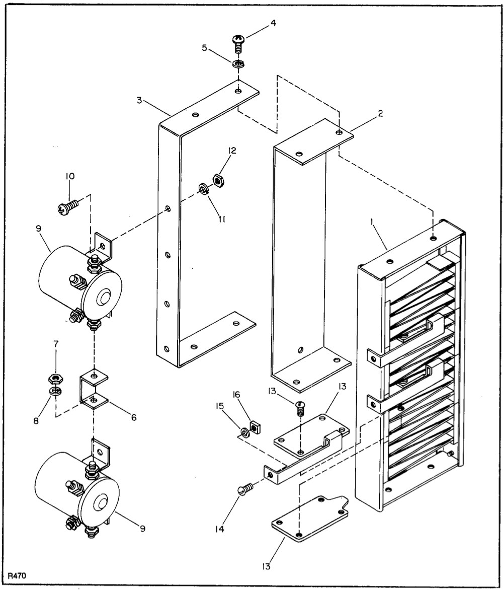
Figure 3-30. Speed Control Resistor Assembly (Serial Number 70875 and Higher)
INDEX NO. |
PART NO. |
PART NAME |
NO. REQD. |
|
502370 |
Resistor Assembly |
1 |
1 |
018900 |
Speed Control Resistor |
1 |
2 |
250731 |
Speed Control Bracket |
1 |
3 |
101284 |
Bracket |
1 |
4 |
070476 |
Round Hd Phillips Screw, ¼-20 x ½ |
4 |
5 |
077209 |
Lock Washer, ¼ |
4 |
6 |
305407 |
Bus Bar |
1 |
7 |
059427 |
Hex Nut, 5/16-18 |
6 |
8 |
077210 |
Lock Washer, 5/16 |
6 |
9 |
020419 |
Solenoid |
2 |
10 |
070476 |
Round Hd Phillips Screw, ¼-20 x ½ |
4 |
11 |
077209 |
Lock Washer, ¼ |
4 |
12 |
059421 |
Hex Nut, ¼-20 |
4 |
13 |
021221 |
Terminal Assy with Screw |
3 |
14 |
068475 |
Round Hd Screw, ¼-20 x 3/8 |
3 |
15 |
077209 |
Lock Washer, ¼ |
3 |
16 |
059813 |
Square Nut, ¼-20 |
3 |
|
3-26. Battery Connector Group Replacement. (Figure 3-31) The battery connector group makes it possible to quickly disconnect the entire electrical circuitry from the battery by means of the quick-disconnect plug. Refer to figures 3-28 or 3-31 for location and replacement of parts in this group. 3-27. METAL SERVICE COVER a. This paragraph covers modification procedures to adapt pallet trucks (serial number 83008 and lower) |
to accommodate the new metal service cover (503731). All parts necessary for the modification are contained in kit number 900696. The plastic service cover (056556) will not be available as a replacement part. b. Modification Procedure In order to fit the metal service cover to trucks supplied with the plastic cover, refer to figures 3-32 through 3-35 and follow this procedure: 1. Remove plastic service cover. |
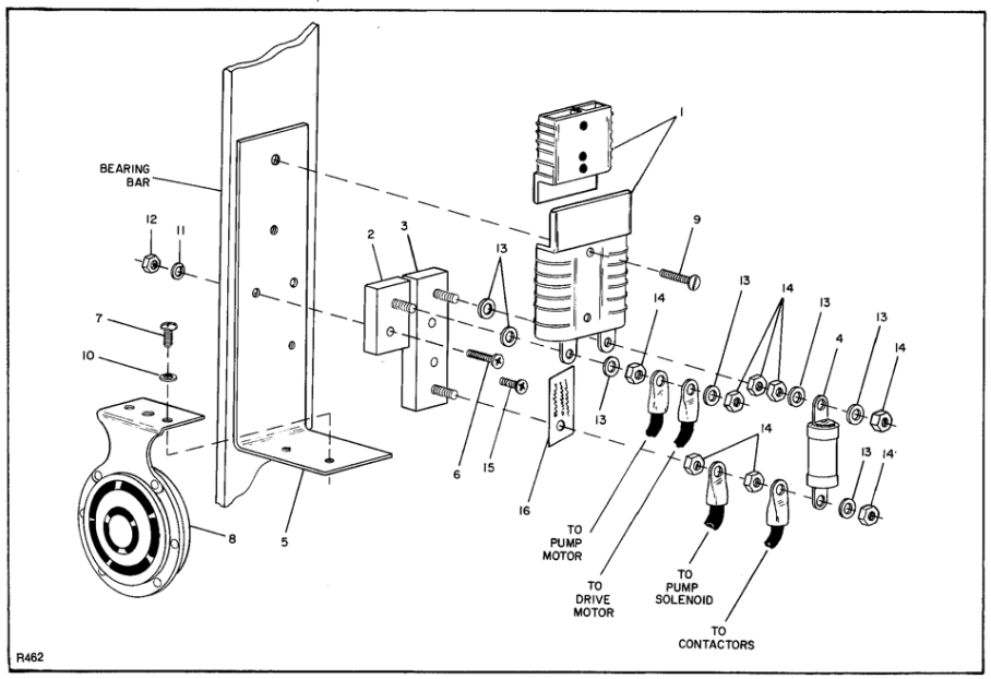
Figure 3-31. Battery Connector Group and Horn (Serial Number 70875 and Higher)
INDEX NO. |
PART NO. |
PART NAME |
NO. REQD. |
INDEX NO. |
PART NO. |
PART NAME |
NO. REQD. |
|
501607 |
Battery Connector Group |
1 |
8 |
009600 |
Horn |
1 |
1 |
005401 |
Battery Connector |
1 |
9 |
068480 |
Round Hd Screw, ¼-28 x 1 |
2 |
2 |
800069 |
Fuse Block (One stud) |
1 |
10 |
077209 |
Lock Washer, ¼ |
2 |
3 |
008902 |
Fuse Block (Two studs) |
1 |
11 |
077209 |
Lock Washer, ¼ |
2 |
4 |
008906 |
Fuse, 300-A |
1 |
12 |
059421 |
Hex Nut, ¼-20 |
2 |
5 |
111765 |
Bracket |
1 |
13 |
077105 |
Washer |
7 |
6 |
069484 |
Flat Hd Phillips Screw, ¼-20 x 2 |
2 |
14 |
059425 |
Hex Nut |
8 |
7 |
070476 |
Round Hd Phillips Screw, ¼-20 x 1/2 |
2 |
15 |
069478 |
Flat Hd Phillips Screw, ¼-20 x 3/4 |
1 |
|
16 |
056507 |
LAbel |
1 |
|||
|
NOTE: Cover brackets (401106) are not used on narrow-straddle models. Proceed to step 3 if fitting metal cover to narrow straddle truck. 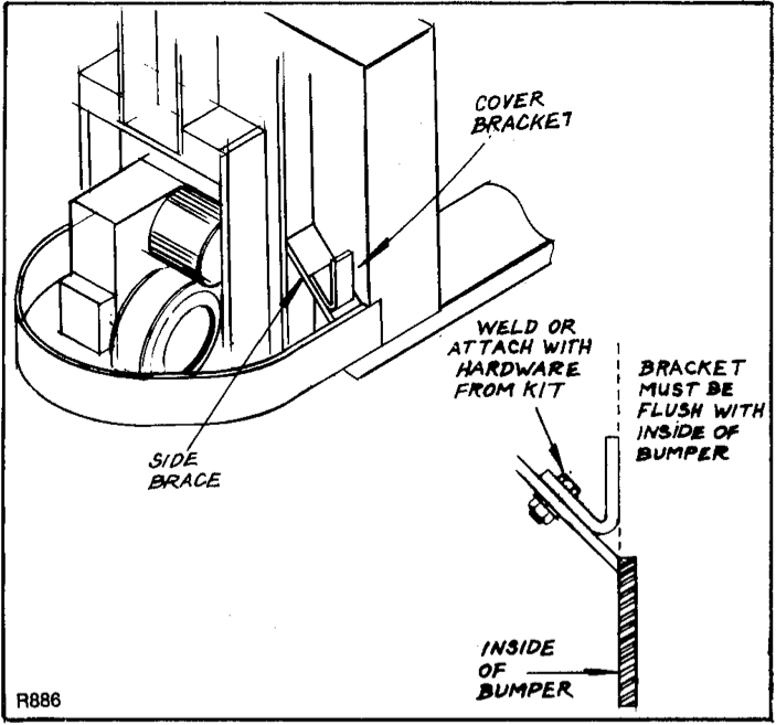 Figure 3-32. Metal Service Kit Bracket 3. Place metal cover onto truck. Since the cover will be used as a template for drilling mounting holes, be certain that the cover is straight, that tab at bottom is tight against inside of bumper, and that holes at the side of cover line up with cover brackets (side braces on narrow-straddle trucks). 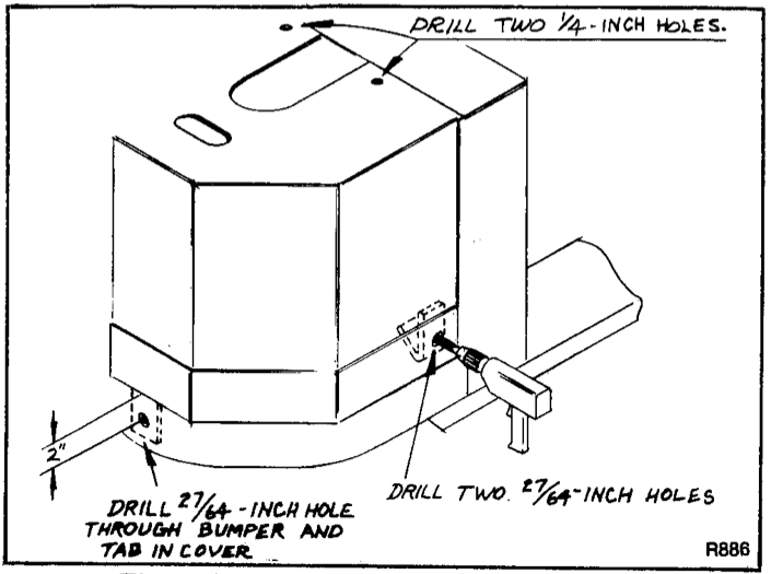 Figure 3-33. Bracket and Cover Drilling |
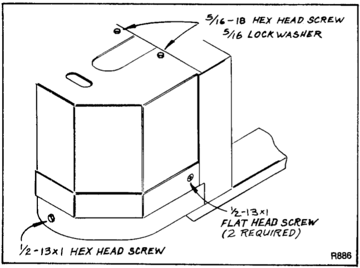
bumper, measure two inches down from cover and drill 27/64-inch hole through bumper and tab. 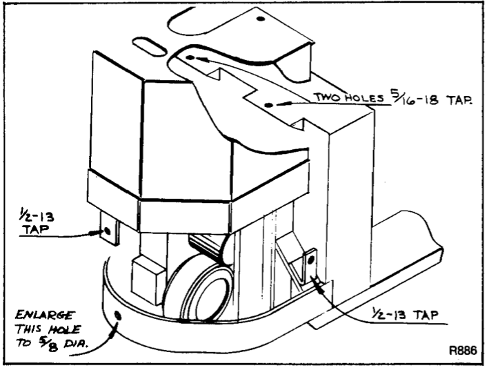 3-34. Tapping Diagram 7. Place cover on truck and attach with hardware as shown in figure 3-35.
|

*Click on link to see original document: