DP OPERATION • MAINTENANCE • REPAIR PARTS LIST PPT POWERED PALLET TRUCK PPT SERIES [PPT_40-0278] 1/2
This article provides a comprehensive list of operation, maintenance, and repair parts for the PPT Series of PPT powered pallet trucks, including the model number [PPT_40-0278].

Written by Nash Bernardo
Updated at July 29th, 2025

TECHNICAL MANUAL
POWERED
PALLET
TRUCK
PPT SERIES
TABLE OF CONTENTS | |||||
SECTION |
|
PAGE |
SECTION |
|
PAGE |
|
PREPARATION FOR USE |
1-1 |
III |
MAINTENANCE AND MAINTENANCE PARTS (CONTINUED) |
|
I |
DESCRIPTION |
1-2 |
3-5 |
Battery Care |
3-2 |
1-1 |
Introduction |
1-2 |
3-6 |
Lubrication |
3-2 |
1-2 |
Description |
1-2 |
3-7 |
Troubleshooting |
3-4 |
1-3 |
General |
1-2 |
3-8 |
Adjustment and Repair |
3-8 |
1-4 |
Capabilities |
1-2 |
3-9 |
Belly-Button Safety Switch Adjustment |
3-8 |
1-5 |
Safety Features |
1-2 |
3-10 |
Control Head Switch Replacement |
3-8 |
1-6 |
Options |
1-2 |
3-11 |
Steering Arm |
3-10 |
II |
OPERATION |
|
3-12 |
Electrical Control Cable Replacement |
3-12 |
2-1 |
General |
2-1 |
3-13 |
Mechanical Brakes |
3-13 |
2-2 |
Operating Precautions |
2-1 |
3-14 |
Drive Motor Repair |
3-17 |
2-3 |
Driving and Stopping |
2-1 |
3-15 |
Chassis and Pivot Assemblies |
3-17 |
2-4 |
General |
2-1 |
3-16 |
Wheel Housings and Exit Rollers |
3-28 |
2-5 |
Driving and Stopping Procedures |
2-2 |
3-17 |
Saucer Assembly and Caster Replacement |
3-29 |
2-6 |
Belly-Button Safety Guard |
2-3 |
3-18 |
Load Wheel Replacement |
3-30 |
2-7 |
Dynamic Brake |
2-3 |
3-19 |
Transmission Repair |
3-30 |
2-8 |
Steering Arm Return Spring |
2-3 |
3-20 |
Drive Wheel Replacement |
3-31 |
2-9 |
Various Stopping Methods |
2-3 |
3-21 |
Hydraulic System Repair |
3-34 |
2-10 |
Operating Lift |
2-3 |
3-22 |
Hydraulic Pump-Motor-Reservoir Assembly |
3-36 |
2-11 |
Loading and Unloading |
2-3 |
3-23 |
Lift Cylinder Repair |
3-38 |
2-12 |
Parking |
2-3 |
3-24 |
Contactor Tip Replacement |
3-40 |
III |
MAINTENANCE AND MAINTENANCE PARTS |
|
3-25 |
Speed Control Resistor Adjustment |
3-40 |
3-1 |
General |
3-1 |
3-26 |
Battery Connector Group Replacement |
3-45 |
3-2 |
Part Number Identification |
3-1 |
3-27 |
Metal Service Cover |
3-45 |
3-3 |
Preventive Maintenance |
3-1 |
|
||
3-4 |
Inspection and Service |
3-1 |
|||
LIST OF ILLUSTRATIONS | |||||
Figure |
|
Page |
Figure |
|
Page |
1-1 |
Powered Pallet Truck, Model PPT-40 |
1-2 |
3-20 |
Hydraulic System (Serial Number 81936 and Lower) |
3-34 |
2-1 |
Steering Arm Controls |
2-1 |
3-21 |
Hydraulic System (Serial Number 81937 and Higher) |
3-35 |
2-2 |
Speed Control |
2-1 |
3-22 |
Pump-Motor-Reservoir Assembly (Serial Numbers 81936 and Lower) |
3-36 |
2-3 |
Mechanical Brake Application |
2-2 |
3-23 |
Pump-Motor-Reservoir Assembly (Serial Numbers 81937 and Higher) |
3-37 |
3-1 |
Lubrication Points |
3-3 |
3-24 |
Lift Cylinder P/N 047552 |
3-38 |
3-2 |
Schematic Diagram |
3-7 |
3-25 |
Lift Cylinder P/N 047564 |
3-39 |
3-3 |
Belly-Button Safety Switch Adjustment |
3-8 |
3-26 |
70-Amp Contactor Wire Terminations |
3-40 |
3-4 |
Control Head |
3-9 |
3-27 |
70-Amp Contactor Tip Replacement |
3-41 |
3-5 |
Pivot Tube and Steering Arm |
3-11 |
3-28 |
Electrical Control Components and Battery Connector Group (Serial Number 67146 to 70874) |
3-42 |
3-6 |
Electrical Control Cable Replacement |
3-12 |
3-29 |
Contactor Panel (Serial Number 70875 and Higher) |
3-43 |
3-7 |
Mechanical Brake Adjustment |
3-13 |
3-30 |
Speed Control Resistor Assembly (Serial Number 70875 and Higher) |
3-44 |
3-8 |
Drum Brake and Linkage |
3-15 |
3-31 |
Battery Connector Group and Horn (Serial Number 70875 and Higher) |
3-45 |
3-9 |
Disk Brake and Linkage |
3-16 |
3-32 |
Metal Service Kit Bracket |
3-46 |
3-10 |
Drive Motor |
3-17 |
3-33 |
Bracket and Cover Drilling |
3-46 |
3-11 |
Standard Chassis and Pivot Assembly (Eccentric Adjusted Push Rods) |
3-22 |
3-34 |
Tapping Diagram |
3-46 |
3-12 |
Standard Chassis and Pivot Assembly (Universal Push Rods) |
3-24 |
3-35 |
Service Cover Assembly |
3-46 |
3-13 |
Narrow Straddle Chassis and Pivot Assembly |
3-26 |
|
||
3-14 |
Straddle and Pivot Blocks |
3-28 |
|||
3-15 |
Modification of Wheel Housing Casting |
3-29 |
|||
3-16 |
Special Length Push Rods |
3-29 |
|||
3-17 |
Caster Assembly |
3-30 |
|||
3-18 |
Tandem Load Wheels |
3-31 |
|||
3-19 |
Transmission and Drive Wheel |
3-32 |
|||
LIST OF TABLES | |||||
Table |
|
Page |
Table |
|
Page |
3-1 |
Inspection and Service Chart |
3-1 |
3-3 |
Lubrication |
3-3 |
3-2 |
Recommended Lubricants |
3-2 |
3-4 |
Troubleshooting Chart |
3-4 |
PREPARATION FOR USE
Upon receipt, visually inspect pallet truck and battery charger. if any damage is found, report it to the carrier and to your big joe dealer immediately. |
Refer to Section II for operating instructions to test the following controls. Belly-Button Safety Switch |
SECTION I
DESCRIPTION
|
1-1. INTRODUCTION. 1-3. General. |
1-5. Safety Features. 1-6. Options. |

Figure 1-1. Powered Pallet Truck, Model PPT-40
SECTION II
OPERATION
|
2-1. GENERAL. Improper operation of the PPT-40 may result in operator injury, or load damage to the truck and/or load. Observe the following precautions when operating the truck. |
5. Never hold the dynamic brake pushbutton on longer than five seconds. 6. Use care when moving a load. Driving the truck too quickly around a turn may upset the balance of the load. 7. Apply the mechanical brake gently except in cases of emergency. 2-3. DRIVING AND STOPPING. 2-4. General. The speed control (see figure 2-1) located inside the belly-button safety-guard provides fingertip control for driving the truck. As the upper portion of the speed control is pressed, it closes contacts for first speed in forward direction. Pressing the speed control farther closes contacts for second and then third speeds (see figure 2-2). The lower portion of the speed control governs the three reverse speeds in the same manner. The truck will start in first speed even in the speed control is pressed immediately to its maximum position. The solid- |
|
 Figure 2-2. Speed Control |

|
state speed control circuit delays the second-speed contactor until the truck has traveled in first speed for one full second. It also delays the third-speed contactor until the truck has traveled in second speed for a minimum of two seconds. The THIRD SPEED, ON/OFF rocker switch is provided to lock out third speed when the truck is being driven unloaded in limited space. The service brake is either an internal expanding-shoe mechanical brake or a disk brake. Lowering the steering arm to horizontal or raising it to vertical applies the mechanical brake (see figure 2-3). All traction power is shut off when the mechanical brake is engaged. When the steering arm is in the upright position by spring action, so that dead-man braking occurs. 2-5. Driving and Stopping Procedures. The following procedure describes driving and stopping the PPT-40. 1. If truck is carrying no load or a light load, turn THIRD SPEED rocker switch (6, figure 2-1) OFF. 2. If carrying no load, lower lift carriage fully for maximum stability when traveling. 3. Grasp the grips of the steering arm so that the speed control can be comfortably operated by either thumb. |
4. Lower the steering arm to a comfortable position above horizontal to disengage the mechanical brake and to energize the electrical circuits. NOTE: Your PPT-40 is equipped with solid-state speed control, therefore a noticeable time lapse occurs between speed changes. 5. To move forward, slowly press the upper (FORWARD) portion of the speed control. Press this control farther to increase speed. 6. To stop, release the speed control and lower the steering arm to the horizontal position. At this position, the brake is lightly applied. Lowering the steering arm below horizontal increases the braking power and de-energizes electrical controls. Applying the mechanical brake in this position is particularly useful on ramps and while moving in tight areas. As noted earlier, the mechanical brake may also be applied by raising the steering arm to the upright position. 7. To travel in reverse, lower steering arm to a comfortable postion and slowlypress lower (REVERSE) portion of speed control. Press this control farther to increase speed in reverse. NOTE: Acceleration in reverse operates in the same manner as that in the forward direction. |
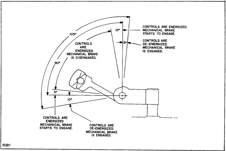
Figure 2-3. Mechanical Brake Application
|
2-6. Belly-Button Safety Guard. The belly-button safety guard minimizes the possibility that the driver might be pinned by the steering arm while driving the truck in reverse. If the safety guard presses against the driver while the truck is being driven in reverse, the safety guard actuates a switch which immediately changes the direction of the truck to forward direction in low speed. 2-7. Dynamic Brake. The dynamic brake is a secondary braking system, completely independent from the mechanical brake, operating only when the steering arm is away from the upright or horizontal positions. Pressing the sTOP pushbuttton applies a constant dc voltage across the drive motor field coils, stopping the motor. The dynamic brake will always bring the truck to a smooth, jar-free stop, except on inclines. 2-8. Steering Arm Return Spring. The steering arm return spring automatically raises the steering arm to the upright position when the steering arm is released. If the steering arm snaps up abruptly, or does not return fully, the steering arm return spring requires adjustment. Refer to Section III for adjustment. 2-9. Various Stopping Methods. There are four different methods for stopping the truck: 1. Release the speed control and allow the truck to coast to a stop. 2. Release speed control and lift or lower steering arm to engage the mechanical brake. The mechanical brake can stop the truck very abruptly if necessary. This brake is also an automatic parking brake. 3. Press the dynamic brake pushbutton. This stops the truck with minimum shock to the load. The dynamic brake is useful for most slowing and stopping functions. 4. While moving, press speed control to low speed in the opposite position. This permits stopping and changing direction very rapidly. This method is called plugging and should be used only for emergency stopping. 2-10. OPERATING LIFT. Two pushbuttons regulate the raising and lowering of the lift carriage. |
CAUTION: To avoid excessive heating and aeration of hydraulic oil, always release UP pushbutton immediately when lift carriage reaches maximum elevation. 1. To raise the lift carriage, depress UP pushbutton and hold it until the lift carriage reaches the desired height, then release the pushbutton. 2. To lower the lift carriage, depress DOWN pushbutton and hold it until the lift carriage reaches the desired height, then release the pushbutton. 2-11. LOADING AND UNLOADING. 1. Lower lift carriage ALL THE WAY DOWN. 2. Lower steering arm and drive truck to the location where the load is to be picked up. 3. Move truck into position so that the forks are within the pallet upright and the load is centered over the forks. 4. Move truck forward to enter pallet and place the load as far back as possible on the forks. Raise the lift carriage to lift the pallet. CAUTION: Avoid spilling the load. Move slowly and use extra care when turning. 5. Drive truck carefully to area where the load is to be placed. 6. Move truck to align the load with its new position. 7. When load is in position, lower the lift carriage to its lowest position, allowing pallet to rest on the floor. 8. Slowly move truck backward, making sure that the forks do not catch on the pallet. 9. Proceed to move the next load. 2-12. PARKING. 1. When finished moving loads, drive truck to its maintenance or storage area. 2. To park the ruck, allow steering arm to return to its upright position which de-energizes the electrical circuits and engages the mechanical brake. 3. Change battery as necessary. Refer to battery care instructions. |
SECTION III
MAINTENANCE AND MAINTENANCE PARTS
|
3-1. GENERAL. This section contains information and procedures for preventive and corrective maintenance of the PPT-40. Preventive maintenance includes periodic inspection, service, and lubrication. Corrective maintenance includes troubleshooting, adjustment, and repair. This section also contains parts lists and illustrations identifying maintenance parts. The callouts on each illustration correspond to the index numbers in the applicable parts list. Each parts list provides the Big Joe Manufacturing Company part number, the part description, and the quantity of the part required in the assembly. When identifying each part to be ordered, visually compare the part in the illustration with the actual part needed. To assure proper identification of each part being ordered, include your truck model number, your truck serial number (check nameplate), the part number, description, and quantity of the part(s) needed. 3-2. PART NUMBER IDENTIFICATION. To determine the part number of a replacement part, identify the assembly in which the part is used and locate the illustration of the applicable assembly. Find the index |
number of the part on the illustration and refer to that index number in the parts list. If the part number is NP, order the next higher assembly. If the part number is VAR, order by part name with truck model number, capacity, lift height, and serial number. If the part number is listed with more than one part number, select the proper part number by comparing the description in the parts list with the specifications of your truck. Refer to the Date Plate to determine application to your truck. 3-3. PREVENTIVE MAINTENANCE. 3-4. Inspection and Service. The design of the PPT-40 provides a long and useful life with a minimum of maintenance. It is important to follow the operating instructions carefully and not to exceed the rated capacity of the truck. Follow the maintenance and lubrication procedures presented in this chapter to keep the equipment in top operating condition. Table 3-1 is an inspection and service chart based on normal usage of equipment eight hours per day, five days per week. If the truck is used in excess of forty hours per week, the frequency of inspection and service should be increased accordingly. |
Table 3-1. Inspection and Service Chart
INTERVAL |
INSPECTION OR SERVICE |
SERVICE REFERENCE |
Daily |
Check battery. |
Paragraph 3-5 |
Daily |
Check operation of belly-button safety switch. |
Paragraph 2-6 |
Daily |
Observe performance of truck. Investigate any improper operation. |
------ |
Weekly |
Lubricate. |
Paragraph 3-6 |
Monthly |
Check transmission oil level. |
Table 3-3 |
Monthly |
Check seals and O-rings for oil leaks. |
Figures 3-19, 3-22 thru 3-25 |
Monthly |
Check hydraulic system oil level. Check hoses and fittings for leaks. |
Table 3-3 |
Monthly |
Check condition to drive motor commutator, brushes, and springs. |
Paragraph 3-14 |
Monthly |
Check condition of pump motor commutator, brushes and springs. |
Paragraph 3-22 |
Monthly |
Check mechanical brake for proper operation. Inspect brake shoes or brake pads and replace if required. |
Paragraph 3-13 |
Monthly |
Check load wheels for wear. |
Paragraph 3-18 |
Monthly |
Check drive wheel for wear. |
Paragraph 3-20 |
Monthly |
Check caster wheels or saucer assemblies for wear. |
Paragraph 3-17 |
Monthly |
Inspect wiring for loose connections and damaged insulation. |
------ |
Monthly |
Inspect contactor tips for excessive pitting and wear. |
Paragraph 3-24 |
Monthly |
Check power cutoff switch for proper operation. |
Figure 3-8 |
Quarterly |
Check lift cylinder wiper ring and packing. |
Paragraph |
Quarterly |
Check for excessive jerking of steering arm when starting or stopping. |
Replace upper and lower pivot tube bearings (Figure 3-5) |
3-5. Battery Care. |
5. When battery is properly charged, return truck to operating readiness.
|
Figure 3-1. Lubrication Points
Table 3-3. Lubrication
FIG. 3-1 R1EF. |
ITEM |
METHOD OF APPLICATION |
LUBRICANT (TABLE 3-2) |
NOTES |
1 |
Upper pivot assembly (3 places on early models, 4 places on current models) |
Gun |
No. 2 |
Grease with pressure gun. |
2 |
Left-hand and right-hand pivot assembly (3 places each) |
Gun |
No. 2 |
Grease with pressure gun. |
3 |
Wheel housings (2 places each) |
Gun |
No. 2 |
Grease with pressure gun. |
4 |
Steering arm elbow |
Can |
No. 4 |
1 or 2 drops |
5 |
Pivot tube |
See note |
No. 2 |
Repack bearings. Apply with brush on moving parts. |
6 |
Transmission |
Funnel |
No. 1 |
Remove plug and check level. Fill to fill line. |
7 |
Hydraulic System |
Funnel |
No. 3 |
Fill with hydraulic oil so that level is seen in street elbow of reservoir when forks are in lowest position. |
- |
Drive Motor, Pump Motor, Load Wheels, Casters |
--- |
--- |
Bearing sealed. No lubrication required. |
3-7. TROUBLESHOOTING. |
trouble with lifting or lowering, and miscellaneous troubles. Refer to the electrical schematic for your truck (figure 3-2) as a supplement to the troubleshooting chart or when tracing an electrical circuit. |
Table 3-4. Troubleshooting Chart
MALFUNCTION |
PROBABLE CAUSE |
CORRECTIVE ACTION |
|
TRUCK DEAD Truck will not run forward or in reverse, nor will lift system operate.
|
a.Fuse is blown |
Check 300-A and 15-A fuses and replace if defective. |
b. Battery dead or disconnected. |
Check battery quick-disconnect plug. Check battery (see paragraph 3-5). |
|
c. Defective wiring |
Check for open circuit. Repair as required. |
|
|
TROUBLE WITH TRAVEL Truck does not run forward or reverse. Everything else is normal. |
A loose connection may be the cause of malfunction.
|
Check all wiring. Tighten all loose connections before further troubleshooting. |
a.Shorted dynamic brake switch or dynamic brake relay. |
Check brake switch and relay, and replace if defective. |
|
b. Defective power cutoff switch. |
Check and replace if required. |
|
c. Center blade of speed control switch broken. |
Check and replace blade or switch if required. |
|
d. Shorted optional travel cutout switch. |
Check and replace if required. |
|
Truck runs forward, but not in reverse. |
Defective speed control switch or defective contactor. |
Check for positive dc voltage at wire number 1 on reverse contactor. If not present when steering arm is in reverse, speed control switch is defective. If voltage is present, contactor is defective. |
Truck runs in reverse, but not forward. |
Defective speed control switch or contactor. |
Check for positive dc voltage at number 2 wire on forward contactor. If not present when steering arm is in operating position and speed control is pressed for forward travel, speed control switch is defective. If voltage is present, contactor is defective. |
Truck runs forward and in reverse at slow speed; will not run at higher speeds. |
a.Defective second and/or third speed contactors. |
Check coils for continuity. Check contacts for excessive wear. (A black appearance where tips make contact is normal). Repair or replace as required. |
b. Defective optional time delay relay(s). |
Check for continuity and replace as required. |
|
Truck runs forward and in reverse at second or third speed only. Truck does not move when control is in first speed position. Everything else is normal. |
Defective or open speed control resistor. |
Check for clean, tight connections. Check resistor for continuity and replace or repair as required. |
Truck runs at third speed when control is in the first or second speed position. Everything else is normal. |
a.Shorted speed control resistor.
|
Check wiring resistor. Check for shorted contacts on high speed relay. |
b. Damaged speed control switch. |
Check switch blades. |
|
|
TROUBLE WITH BRAKING Mechanical brake does not stop truck properly. |
a.Brake linkage in need of adjustment. |
Adjust mechanical brake (see paragraph 3-13). |
b. Brake shoes or disc brake pads worn. |
Replace shoes or pads and readjust mechanical brake. |
|
Mechanical brake grabs when steering arm is in operating position. |
Brake linkage overadjusted. |
Adjust mechanical brake (see paragraph 3-13). |
Dynamic brake does not stop truck. |
Defective brake switch, brake relay, or brake resistor. |
If click is heard when dynamic brake pushbutton is pressed, check brake resistor and relay contacts. If no click, check brake switch and coil of relay. Repair or replace defective part. |
TROUBLE WITH LIFTING OR LOWERING |
|
Check hydraulic oil level. Before further troubleshooting, fill hydraulic reservoir so that oil is seen in street elbow when forks are fully lowered. Tighten all electrical connections. |
Lift carriage does not rise; everything else is normal. |
a.Defect in electrical system. |
If pump motor does not run when UP control is depressed, defect is in pump solenoid or pump motor. Check for positive dc voltage |
b. Defect in hydraulic system. |
Check for pinched hoses. Check pump for proper operation. Replace if necessary. Check for defect in lift cylinder. |
|
Lift carriage does not lower; Everything else is normal. |
Defect in hydraulic system. |
Look for obstruction in the hydraulic line. Check DOWN switch for proper action. Repair as required. |
Forks creep downward under load; everything else is normal. |
Leak in hydraulic system, packing, or valve. |
Check solenoid-operated valve for obstructions. Check pump for leakage back into the reservoir. Repair fittings or replace pump as required. |
|
Oil sprays or flows from top of the lift cylinder.
|
Defective packing in lift cylinder. |
Overhaul the lift cylinder and install new packing, O-rings, and wiper ring. |
Oil splashes out of vent when lowering forks. |
Oil level too high. |
Drain, then refill reservoir when forks are in their lowest position. |
Squealing sounds when forks are raised. |
a.Oil level too low. |
Add oil to reservoir. |
b. Aerated oil (foamy). |
Drain and replace oil. |
|
c. Defective bearing in pump motor or pump. |
Replace bearing or pump. |
|
Forks do not lift to top. |
Oil level too low. |
Add oil to reservoir. |
No motion, slow or jerky action of hydraulic system. |
a.Load heavier than capacity. |
Refer to data plate on side of mast for maximum lift capacity. |
b. Defective lift cylinder. |
Rebuild or replace. |
|
c. Defective pump. |
Check and repair or replace if necessary. |
|
d. Low battery charge. |
Recharge battery. |
|
|
MISCELLANEOUS Steering arm does not return to the upright position. |
a.Return spring improperly adjusted. |
Readjust spring tension (see paragraph 3-11). |
b. Binding brake linkage or electrical cable. |
Check and free binding item. |
|
Truck moves forward in low speed when arm is pulled down. |
a.Belly-button safety switch defective. |
Check for short, and repair or replace as necessary. |
b. Short in control head. |
Check wiring and repair as required. |
|
c. Handle guard tongue causing activation of switch. |
Straighten handle guard tongue. |
|
Steering arm jerks excessively when starting or stopping the truck. |
a.Worn pivot tube bearings. |
Replace upper and lower pivot tube bearings. |
b. Drive wheel tire worn. |
Replace drive wheel. |

Figure 3-2. Schematic Diagram
|
3-8. ADJUSTMENT AND REPAIR 5. To decrease the gap, back off lower locknut and then tighten upper locknut until switch is secure; to increase the gap, back off upper locknut and then tighten lower locknut until switch is secure. |
6. Press the guard, and listen for the click than indicates that the guard has actuated the switch. 7. Repeat steps 4 and 5 until pressing the guard actuates the switch properly. 8. Recheck gap 1/8-inch clearance. 9. Remove the nuts and socket head cap screws which have temporarily secured the guard and strap to the control head assembly. 10. Reinstall control head, guard, and strap on the steering arm, making certain that the spring and two spacers are back in place. 11. Reconnect electrical cable connectors, reinstall steering arm access cover, and reconnect the battery. 3-10. Control Head Switch Replacement. (Figure 3-4) NOTE: Replacement for third speed cutout switch (26, figure 3-4) are different than original equipment. The new switch uses two self tapping screws part number 068178 instead of the machine screws part number 068177. Also the switch opening in mounting plate part number 245734 must be enlarged from 1-3/8 inch to 1-7/16 inch to accomodate the new style switch. 1. Disconnect battery. Remove steering arm access cover (13, figure 3-5) and disconnect electrical cable connectors. NOTE: While removing the control head assembly, two spacers and one spring (needed for reassembly) will fall free. 2. Being careful to catch and retain the spring (14, figure 3-4) and two spacers (21) that fall from the steering arm as the complete control head assembly is removed, remove the four socket head screws (27) and lock washers (28) that secure the control head assembly, strap, and safety guard to the steering arm (16). 3. Replace the speed control switch (22), belly-button safety switch (29), and/or dynamic brake switch (19) as required. NOTE: If the belly-button safety switch is replaced, adjust it in accordance with paragraph 3-9 before reinstalling control head assembly. 4. After replacing defective switch(es), reinstall control head, strap, and safety guard, making certain that the spring (14) and two spacers (21) are put back in place. 5. Reconnect electrical cable connectors and reinstall steering arm access cover. Connect battery. |
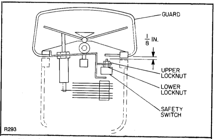
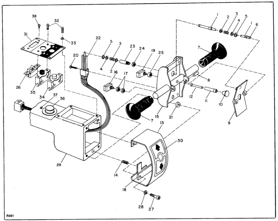
Figure 3-4. Control Head
INDEX NO. |
PART NO. |
PART NAME |
NO. REQD. |
INDEX NO. |
PART NO. |
PART NAME |
NO. REQD. |
|
502194 |
Control Head Assembly |
1 |
22 |
020651 |
Speed Control Assy |
1 |
1 |
061400* |
Switch Plunger |
1 |
|
020682 |
Switch Only (Less harness) |
1 |
2 |
077024* |
Washer, 3/8 x 5/8 x 16 Ga |
2 |
|
005612 |
Center Contact Blade |
1 |
3 |
075023* |
Spring |
2 |
|
005611 |
Outside Contact Blade |
4 |
4 |
077025* |
Washer, 3/8 x 5/8 x 5/64 |
2 |
23 |
057613* |
Plunger Guide |
1 |
5 |
061807* |
Retaining Ring |
2 |
24 |
059674* |
Locknut |
2 |
6 |
058353* |
Connecting Link |
1 |
25 |
074703† |
Spacer |
1 |
7 |
057502 |
Handle Grip |
2 |
26** |
020699 |
Rocker Switch |
1 |
8 |
061002 |
Roll Pin, ¼ x ¾ |
2 |
27 |
065555 |
Socket Hd Cap Screw, 5/16-18 x 1 |
4 |
9 |
500408 |
Speed Control |
1 |
28 |
077210 |
Lock Washer, 5/16 |
4 |
10 |
053200 |
Dynamic Brake Pushbutton |
1 |
29 |
800066 |
Steering Arm (Also 12, Fig. 3-5) |
REF |
11 |
057615 |
Brake Switch Guide |
1 |
30 |
076115 |
Decal |
1 |
12 |
060202 |
Brake Switch Pin |
1 |
31** |
245734 |
Mounting Plate |
1 |
13 |
101171 |
Belly-Button Safety Guard |
1 |
32 |
068177 |
Round Hd Machine Screw, 5-40 x 3/8 |
8 |
14 |
075030 |
Belly-Button Safety Guard Spring |
1 |
33 |
077203 |
Lock Washer, No. 5 |
4 |
15 |
502920 |
Control Head Cover |
1 |
34 |
020698 |
UP Switch (Red) |
1 |
16 |
020710 |
Pushbutton Switch (Belly-button safety) |
1 |
35 |
020697 |
DOWN Switch (Black) |
1 |
17 |
059676 |
Locknut |
2 |
36 |
501972 |
Horn Switch Assy |
1 |
18 |
245748 |
Strap |
1 |
37 |
071376 |
Screw 10-32 x ½ |
2 |
19 |
020710 |
Pushbutton Switch (Dynamic brake) |
1 |
38** |
068178 |
Self Tapping Screw, 4-40 x 5/16 |
2 |
20 |
068185 |
Round Hd Machine Screw, 5-40 x 1-3/8 |
2 |
|
068177 |
Round Head Machine Screw, 5-40 x 3/8 |
2 |
21 |
259103 |
Spacer |
2 |
**See Note at beginning of paragraph 3-10. |
|||
*Included in Speed Control Linkage Kit 900115 |
†Included in Dynamic Brake Linkage Kit 900114 |
||||||
3-11. STEERING ARM (Figure 3-5). |
b. Replacement. |
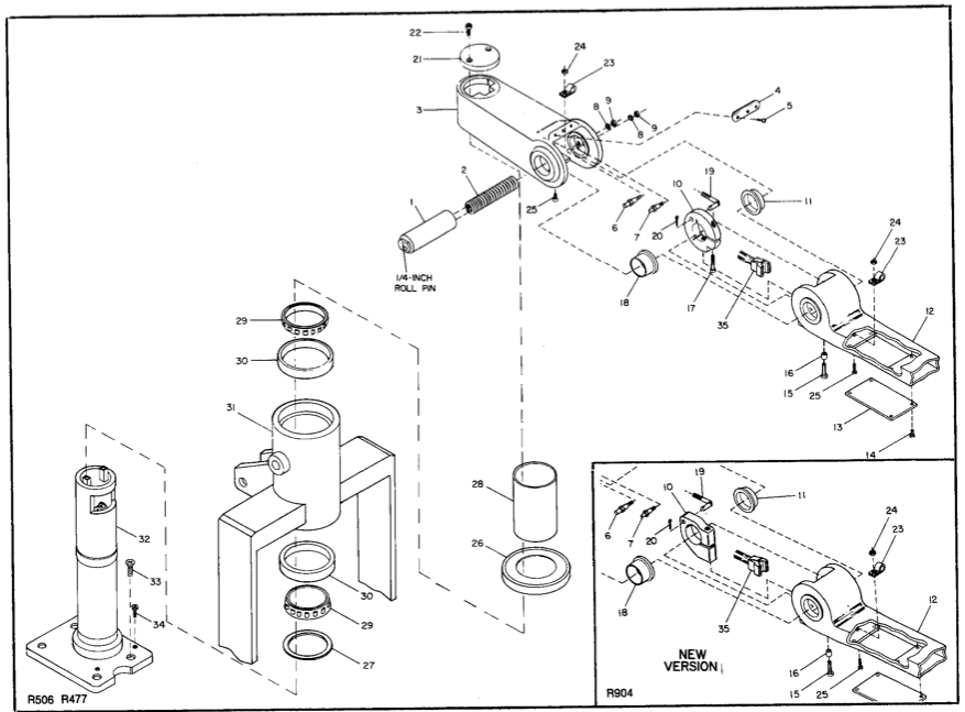
Figure 3-5. Pivot Tube and Steering Arm
INDEX NO. |
PART NO. |
PART NAME |
NO. REQD. |
INDEX NO. |
PART NO. |
PART NAME |
NO. REQD. |
|
501672 |
Steering Arm and Pivot Cap Assy |
1 |
19 |
501396* |
Upper Brake Rod |
1 |
1 |
501371 |
Spring Tube Assy |
1 |
|
501673† |
Upper Brake Rod |
1 |
2 |
075060 |
Steering Arm Return Spring |
1 |
20 |
060417 |
Cotter Pin, 3/32 x ¾ |
1 |
3 |
800064* |
Pivot Cap |
1 |
21 |
191045 |
Pivot Cap Cover |
1 |
|
800070 |
Pivot Cap |
1 |
22 |
065603 |
Socket Hd Screw, 3/8-16 x ¾ |
2 |
4 |
052876 |
Bumper |
1 |
23 |
056116* |
Clamp |
2 |
5 |
062923 |
Pan Hd Screw, 10-32 x 3/8 |
3 |
|
502474† |
Cable Clamp and Speed Nut |
2 |
6 |
285302 |
Spring Pin |
1 |
24 |
059421* |
Hex Nut, ¼-20 |
2 |
7 |
285303 |
Spring Pin |
1 |
25 |
069484** |
Flat Hd Screw, ¼-20 x ¾ |
2 |
8 |
077210 |
Lock Washer, 5/16 |
2 |
|
069484†† |
Phillips Flat Hd Screw, ¼-20 x 2 |
2 |
9 |
059426 |
Hex Nut, 5/16-18 |
2 |
26 |
800063 |
Dust Cover |
1 |
10 |
311401▲ |
Tube Clamp |
1 |
27 |
073511 |
Seal |
1 |
|
800204 |
Tube Clamp |
1 |
28 |
312101 |
Yoke Cap Tube |
1 |
11 |
052922 |
Flanged Bushing |
1 |
29 |
051193 |
Bearing Cone |
2 |
12 |
800066 |
Steering Arm (Also 16, fig. 3-4) |
1 |
30 |
051192 |
Bearing Cup |
2 |
13 |
250718 |
Access Cover |
1 |
31 |
501485** |
Yoke (Also 27, fig. 3-11, sheet 1) |
REF |
14 |
071375 |
Truss Hd Screw |
4 |
|
502502†† |
Yoke (Also 27, fig. 3-11, sheet 2) |
REF |
15 |
065605*** |
Socket Hd Screw, 3/8-16 x 1 |
1 |
32 |
501436 |
Pivot Tube and Mounting Base Assy |
1 |
|
065569 |
Socket Hd Screw, 7/16-14 x 2-1/4 |
1 |
33 |
069710 |
Flat Hd Screw, ½-13 x 1-3/4 |
4 |
16 |
401127 |
Spacer |
1 |
34 |
073480** |
Socket Hd Cap Screw, 5/16-18 x 3/8 |
2 |
|
270508*** |
Flanged Bushing |
1 |
|
065556†† |
Socket Hd Cap Screw, 5/16-18 x ½ |
2 |
17 |
065610*** |
Socket Hd Screw |
1 |
35 |
023041* |
Electrical Control Cable |
1 |
18 |
052925 |
Flanged Bushing |
1 |
|
503201 |
Electrical Control Cable |
1 |
*Serial Numbers below 74733 except 73324 and 73920 |
▲Not available as a replacement part, use 800204 (See para. 3-11) |
||||||
†Serial Numbers 73324, 73920, and 74734 and Higher |
**Standard-Chasses Model |
||||||
***Used with Tube Clamp 311401 only |
††Narrow-Straddle Model |
||||||
|
3-12. Electrical Control Cable Replacement (Figure 3-6) 1. Disconnect battery. 2. Remove steering arm access cover (7). 3. Disconnect the connectors (8, 9). 4. Remove cable clamps (1, 2) and loosen loop of cable that is around the spring tube assembly (3). 5. Remove pivot cap cover (6). 6. Pull loose end of cable up, and let it extend through pivot cap cover opening. 7. Cut off connector (8) from end of cable. 8. Tape the cut end of the old cable to the terminal end of the new cable. 9. Grease the new cable with a lithium base grease or silicone spray. NOTE: Tag all wires with destination before disconnecting to insure proper reconnection. 10. Remove service cover and detach terminal end of old cable from all points of connection. 11. Draw new cable into pivot tube by pulling old cable out through the opening in transmission housing. NOTE: The cable leads are numbered consecutively. 12. Disconnect the old cable from the new cable and connect the new cable terminals sequentially. 13. Wipe off excess grease or silicone spray from exposed parts of the cable. 14. Pull the connector end of the cable under spring tube assembly (3) and out the opening at the elbow. 15. Eliminate cable slack in pivot tube; then secure cable with cable clamp (1). 16. Loop cable around spring tube assembly as illustrated and push connector end of cable into steering arm. CAUTION: Improper cable loop adjustment will damage the cable. If too tight, the cable will tear when the steering arm is in the up position. If too loose, the cable will buckle or be pinched when the steering arm is in the down position. 17. Pull the cable, grasping it through the steering arm access hole, until the cable is wrapped firmly around the spring tube assembly (3). Slack off approximately ½ inch and secure the cable in this position with cable clamp (2). |
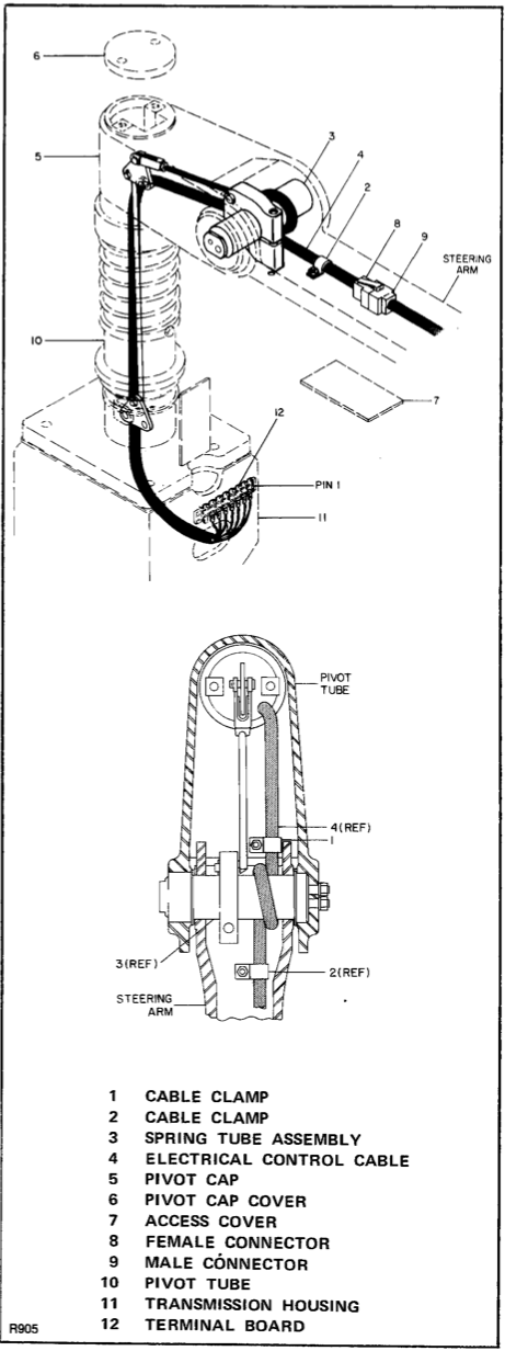 Figure 3-6. Electrical Control Cable Replacement |
|
18. Work steering arm up and down a few times to assure that the electrical control cable is not binding. 19. Connect the two cable connectors at the steering arm access opening. 20. Reinstall the steering arm access cover (7), pivot cap cover (6), and service cover. 21. Reconnect battery. 3-13 Mechanical Brakes. Adjust the mechanical brake if it does not begin to hold when the steering arm is raised to within 15 degrees from its park position or lowered to within 15 degrees from its lowest position (See Figure 3-7A). Proceed as follows: a. Drum Brake Adjustment (figure 3-7A & B) 1. Disconnect battery. 2. Jack up the truck so the drive wheel is off the ground, then securely block the truck to prevent slipping. |
3. Secure steering arm assembly in a position that is approximately 15 degrees down from its park position or 15 degrees up from its lowest position. 4. Remove service cover. 5. Loosen jam nut (1) on the brake rod (5). 6. While spinning the brake drum or drive wheel by hand, tighten the adjustment nut (2) against the tube (3) until you feel a noticeable drag. 7. Tighten jam nut. If the above adjustment is not adequate, proceed as follows: 8. Loosen castellated nut (6) that holds brake lever (4) to cam (8). 9. Rotate brake lever one or two grooves on the splinned shaft of the cam. 10. Tighten the castellated nut. 11. Repeat steps 5 through 7. NOTE: It may now be necessary to back off on the adjusting nut slightly. |

Figure 3-7. Mechanical Brake Adjustment
|
12. Resecure the steering arm in drive position and spin the drive wheel to be sure there is no drag. 13. Return the truck to operating condition. b. Disc Brake Adjustment (Figure 3-7A & C) 1. Disconnect battery. 2. Jack up the truck so the drive wheel is off the ground, then securely block the truck to prevent slipping. 3. Secure steering arm assembly in a position that is approximately 15 degrees down from its park position or 15 degrees up from its lowest position. 4. Remove service cover. 5. Spin drive wheel by hand and position weldment tube (1) by adjusting nuts (2) until you feel a noticeable drag. 6. Tighten nuts (2) to secure adjustment. 7. Resecure the steering arm in drive position and spin the drive wheel to be sure there is no drag. 8. Return the truck to operating condition. c. Replacement of Drum Brake Shoe (Figure 308) 1. Block the wheels to prevent the truck from rolling. 2. Remove service cover. 3. Secure the steering arm down from its park position so that the mechanical brake is disengaged. 4. Loosen and remove locknut (39) and lock washer (38). 5. Pull the brake drum (37) from the drive motor shaft, being careful to retain key (36). 6. Remove brake shoe return spring (32) and both brake shoe hold-down springs (29). 7. Remove both brake shoes (33). 8. Replace worn brake shoes (33). and reverse disassembly procedure to assembly. 9. Release steering arm. 10. Refer to paragraph a and adjust brake. d. Replacement of Disc Brake Parts. (Figure 3-9) 1. Block the wheels to prevent the truck from rolling. 2. Secure the steering arm down from its park position so that the mechanical brake is disengaged. 3. Remove service cover. 4. Remove two bolts (26) and nuts (25) to release brake pads (27). |
5. If brake pads don't fall free, slide brake pads out from end of clamp (24). 6. Insert replacement brake pads in clamp assembly, one pad on each side of disc (30) with linings toward the disc, and secure pads and clamp with two bolts (26) and nuts (25). 7. Release steering arm. 8. Refer to paragraph a and adjust brake. e. Brake Lever Replacement. (Figure 3-9) 1. Block the wheels to prevent the truck from rolling. 2. Remove service cover. 3. Position steering arm to the left as far as possible and secure the steering arm down from its park position so that the mechanical brake is disengaged. NOTE: The brake lever has a pin that fits into one of two slots on the insode of the clamp assembly. 4. Check position of brake lever pin (23) inside the clamp assembly so that you will be sure to place brake lever pin in correct slot during reassembly. 5. Release brake lever (23) from weldment tube (22) by removing cotter pin (3) from weldment tube stub. NOTE: The brake pads may fall free during the next step. 6. Remove two bolts (26) and nuts (25) to release brake clamp (24) from mounting plate (34). 7. If brake pads did not fall free, slide the brake pads (27) out from end of clamp and slide the brake lever (23) out through the brake lever access hole located on the opposite side of the clamp. 8. Check that replacement brake lever has pin tightly secured. 9. Slide the brake lever (23) through the brake lever access hole located on the opposite side of the clamp and align the brake lever so that the pin is in the proper pin slot. 10. Slide clamp (24) on mounting plate (34) so that mounting plate is at lever side of clamp, reinstall brake pads (27), one pad on each side of disc, reinstall brake pads (27), one pad on each side of disc (30) with linings toward the disc, and check that pin in lever is in proper slot of the clamp. 11. Secure clamp to mounting plate with two bolts (26) and nuts (25). 12. Slide brake lever hole over weldment tube stub and secure with cotter pin. 13. Adjust the brake in accordance with paragraph b. |
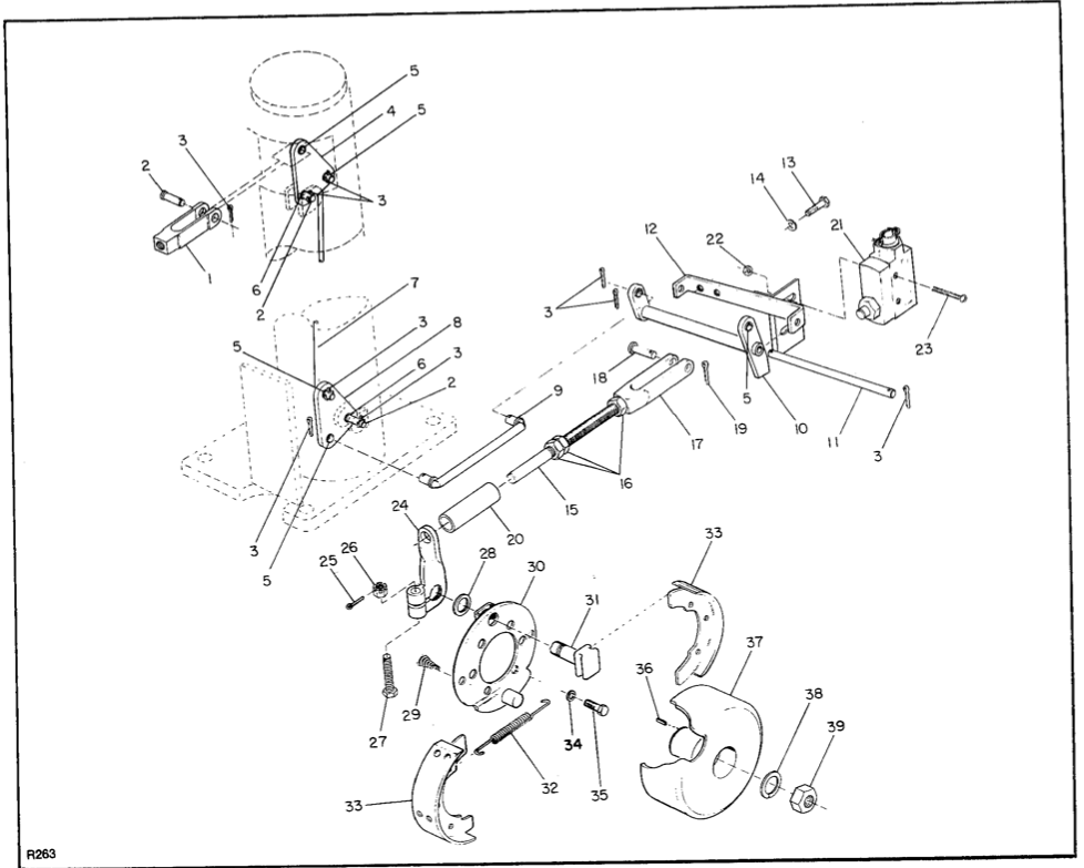
Figure 3-8. Drum Brake and Linkage (Serial Number 70595 and Lower)
INDEX NO. |
PART NO. |
PART NAME |
NO. REQD. |
INDEX NO. |
PART NO. |
PART NAME |
NO. REQD. |
1 |
056200 |
Clevis |
1 |
22 |
059412 |
Hex Nut, 6-32 |
2 |
2 |
060300 |
Clevis Pin |
3 |
23 |
068336 |
Round Hd Screw, 6-32 x 1-1/2 |
2 |
3 |
060417 |
Cotter Pin |
9 |
|
052850 |
Mechanical Brake Assy |
1 |
4 |
111104 |
Upper Pivot Plate |
1 |
24 |
050602 |
Brake Lever |
1 |
5 |
053109 |
Lock Bushing |
6 |
25 |
060403 |
Cotter Pin |
1 |
6 |
053106 |
Flanged Bushing |
2 |
26 |
059723 |
Slotted Hex Nut, ¼-28 |
1 |
7 |
500201 |
Tube Brake Rod |
1 |
27 |
063531 |
Hex Hd Cap Screw, ¼-28 |
1 |
8 |
111105 |
Lower Pivot Plate |
1 |
28 |
077034 |
Flat Washer, ½ |
1 |
9 |
500202 |
Brake Rod |
1 |
29 |
075029 |
Brake Shoe Hold-Down Spring |
2 |
10 |
500424 |
Lower Level Assy |
1 |
30 |
061308 |
Brake Backing Plate |
1 |
11 |
258107 |
Pivot Pin |
1 |
31 |
053352 |
Cam Shaft |
1 |
12 |
500197 |
Mounting Bracket Assy |
1 |
32 |
075028 |
Brake Shoe Return Spring |
2 |
13 |
063605 |
Hex Hd Cap Screw, 3/8-16 x 1 |
2 |
33 |
074401 |
Brake Shoe |
2 |
14 |
077211 |
Lock Washer, 3/8 |
2 |
34 |
077210 |
Lock Washer, 5/16 |
5 |
|
500508 |
Rod Assy |
1 |
35 |
063552 |
Hex Hd Cap Screw, 5/16-18 x 5/8 |
5 |
15 |
258108 |
Rod |
1 |
36 |
057900 |
Key, ¼ x ¼ x 1-1/8 |
1 |
16 |
059427 |
Hex Nut, 5/16-24 |
3 |
37 |
500406 |
Brake Drum |
1 |
17 |
056200 |
Clevis |
1 |
38 |
077215 |
Lock Washer, 5/8 |
1 |
18 |
060300 |
Clevis Pin |
1 |
39 |
059645 |
Locknut, 5/8-18 |
1 |
19 |
060417 |
Cotter Pin |
1 |
|
|||
20 |
238508 |
Spacer |
1 |
||||
21 |
020729 |
Power Cutoff Switch |
1 |
||||
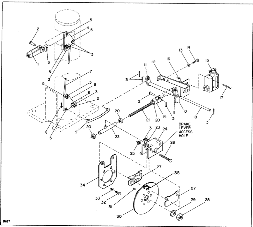
Figure 3-9. Disc Brake and Linkage (Serial Number 70596 and Higher)
INDEX NO. |
PART NO. |
PART NAME |
NO. REQD. |
INDEX NO. |
PART NO. |
PART NAME |
NO. REQD. |
1 |
056200 |
Clevis |
1 |
19 |
800119 |
Clevis |
1 |
2 |
060300 |
Clevis Pin, 5/16 x 5/16 |
4 |
20 |
059427 |
Hex Nut, 5/16-24 |
3 |
3 |
060417 |
Cotter Pin, 3/32 x ¾ |
11 |
21 |
258121 |
Rod |
1 |
4 |
111104 |
Upper Pivot Plate |
1 |
22 |
502814 |
Weldment Tube |
1 |
5 |
053109 |
Lock Bushing |
4 |
|
052857 |
Clamp Assy |
1 |
6 |
053106 |
Flanged Bushing |
2 |
23 |
052860 |
Brake Lever with Pin |
1 |
7 |
500201 |
Tube Brake Rod |
1 |
24 |
052863 |
Brake Clamp |
1 |
8 |
111105 |
Lower Pivot Plate |
1 |
25 |
052862 |
Hex Nut |
2 |
9 |
500202 |
Brake Rod |
1 |
26 |
052861 |
Hex Hd Bolt |
2 |
10 |
500424 |
Lower Level Assy |
1 |
27 |
052859 |
Brake Pad |
2 |
11 |
053109 |
Lock Bushing |
2 |
28 |
059645 |
Locknut, 5/8-18 |
1 |
12 |
500197 |
Mounting Bracket Assy |
1 |
29 |
077215 |
Lock Washer, 5/8 |
1 |
13 |
077211 |
Lock Washer, 3/8 |
2 |
30 |
503083 |
Disc Assy |
1 |
14 |
063605 |
Hex Hd Cap Screw, 3/8-16 x 1 |
2 |
31 |
057900 |
Key, ¼ x ¼ x 1-1/8 |
1 |
15 |
020729 |
Power Cutoff Switch |
1 |
32 |
063552 |
Hex Hd Cap Screw, 5/16-18 x 5/8 |
6 |
16 |
059412 |
Hex Nut, 6-32 |
2 |
33 |
077210 |
Lock Washer, 5/16 |
6 |
17 |
068336 |
Round Hd Screw, 6-32 x 1-1/2 |
2 |
34 |
111706 |
Mounting Plate |
1 |
18 |
258107 |
Pivot Pin |
1 |
35 |
075070 |
Spring |
2 |
|
3-14 Drive Motor Repair. (Figure 3-10) The drive motor requires no periodic maintenance. If the truck does not run the drive motor is at fault, remove cover band (12, figure 3-10) and then inspect brushes (9) and commutator (on armature). Replace brushes if they are worn. Clean commutator of rought spots with a fine emery cloth and remove accumulations of loose particles. If the motor is to be disassembled, remove it from the transmission as follows: 1. Disconnect battery. 2. Remove brake unit. For trucks with drum brake, remove shoes (paragraph 3-13c). Then remove cotter pin (19, figure 3-8) and clevis pin (18), separating the rod clevis from the lower liner assembly. For trucks with disc brake, remove pads 9paragraph 3-13d). Then remove lock nut (28, figure 3-9) and lock washer (29). Pull disc (30) from drive motor shaft being careful to retain key (31). 3. Make sure the four cables to the drive motor are properly labeled A1, A2, F1, and F2; then disconnect the cables from the drive motor. 4. Remove the two screws and washers which secure the motor to the transmission housing. 5. Transfer motor and attached brake parts to suitable workbench. |
6. Continue disassembly of motor, using figure 3-10 as a guide. 3-15. CHASSIS AND PIVOT ASSEMBLIES. a. General. It is essential to proper truck operation that the pivot assemblies are in good working order and kept properly adjusted. Beginning with truck serial number 83307, all standard chassis trucks except those with tandem load wheels have the new style universal push rods. These push rods offer a greater range of adjustment and simplify determining push rod replacement number. The older style eccentric-adjusted push rod (on trucks serial number 83306 and lower and all trucks with tandem load wheels) has shown to be durable and long lasting, but does not offer the ease of service of the universal push rods. The following paragraphs detail procedures for removal, installation and adjustment of the yoke assembly, pivot assemblies and both style push rods. If you wish to retrofit an older standard chassis PPT-40 truck with the universal push rods, follow the procedures for removing the eccentric type and for installing the universal type push rods. Trucks with tandem load wheels cannot be retrofitted. Procedures are also included for replacement of pivot blocks. |

Figure 3-10. Drive Motor
INDEX NO. |
PART NO. |
PART NAME |
NO. REQD. |
INDEX NO. |
PART NO. |
PART NAME |
NO. REQD. |
|
016020 |
Drive Motor (MCP-4027) |
1 |
9 |
003709 |
Brush (Set of four) |
1 |
1 |
009400 |
Drive End Head |
1 |
10 |
900136 |
Brush Spring (Set of four) |
1 |
2 |
042110 |
O-ring |
1 |
11 |
900137 |
Commutator End Head |
1 |
3 |
051162 |
Drive End Bearing |
1 |
12 |
005951 |
Cover Band |
1 |
4 |
900133 |
Terminal Stud and Lead Package |
4 |
13 |
059811 |
Square Nut, 10-32 |
1 |
5 |
NP |
Field Coil Package |
1 |
14 |
068409 |
Round Hd Screw, 10-32 x 1-1/2 |
1 |
6 |
001506 |
Armature |
1 |
15 |
065477 |
Socket Hd Screw, ¼-20 x 5/8 |
12 |
7 |
900135 |
Ring and Washer Package |
1 |
16 |
077209 |
Lock Washer, 1/4 |
12 |
8 |
051161 |
Commutator End Bearing |
1 |
|
|||
|
b. Removal of Yoke and Pivot Assemblies. The following procedure is recommended for disassembly of the pivot arms and yoke. 1. Disconnect battery. Leave steering arm in its position. 2. Securely block load wheels. Remove service cover. 3. Disconnect the hose from the elbow attached to the pump. NOTE: Locate the harness passing in front of the pivot tube which contains the two heavy gauge battery cables and three small diameter wires. 4. Disconnect the two heavy gauge battery cables; one is connected to the negative battery connector and the other to the 300-ampere fuse terminal. 5. Disconnect the harness wires attached to the horn and to the solenoid. 6. Disconnect the remaining wire going to the motor. This can be disconnected at the inline connector which attaches the black wire to the red wire from the motor. 7. Disconnect the mechanical brake by removing the clevis pin that secures the rod clevis to the lower lever assembly. 8. Disconnect brake rod from lower level assembly. 9. Disconnect the lift cylinder from the yoke by removing the bottom shaft (17, figure 3-24 or 3-25) and two snap rings (18) joining them. 10. Attach chains of overhead crane or similar equipment to horizontal bars of yoke. NOTE: Numbers in parenthesis ( ) refer to standard chassis figures 3-11 and 3-12 and numbers in brackets [ ] refer to narrow straddle of figure 3-13. 11. Raise the rear of the truck with jacks or other suitable means to provide access to the lower pivot arm shafts. 12. Remove shafts (23) [14] and (38) [30] their securing pins (8) [6], freeing pivot assemblies from chassis. 13. Use crane to raise the yoke a few inches for better access to pivot assemblies (19) [9] and (24) [33]. 14. To disconnect push rod from lower pivot arm: a. on eccentric-adjusted trucks, remove screw (17, fig. 3-11) being careful not to lose eccentric (18), bushing (21), and lock washer (15). |
b. on universal push rod trucks, remove screw (21, figure 3-12) being sure to retain bushing (18). c. on narrow straddle trucks, slide pivot arm (9, figure 3-13) off spindle on lug weldment (34) being sure to retain bushing (10). 15. Carefully move yoke clear of truck. 16. Further disassembly may be accomplished using figure 3-11, 3-12, or 3-13 as a guide. c. Installation of Yoke. Reinstall the yoke by reversing the removal procedure. On trucks with eccentric-adjusted push rods, lubricate the threads on screw (17, figure 3-11) before reconnecting the push rods to the lower pivot assembly. Tighten screw until just snug, and refer to paragraph 3-15f to adjust eccentric. d. Removal of Eccentric-Adjusted Push Rod. In order to perform the following procedure, the truck must be placed in a service position, either securely held off the floor, or carefully tipped on its side. If proper hoists or jacks are available, lower the lift carriage as far as it will go, raise the truck off the floor and proceed to step 5. If you must tip the truck, perform the following steps. 1. Lower the lift carriage all the way, and then disconnect and remove batteries. 2. Plug the hydraulic reservoir and transmission breather vents with 3/8 NPT pipe plugs. 3. Disconnect the high-pressure hydraulic hose at the pump and place the free end of hose in a clean container to catch the oil that may drain from lift cylinder. 4. Carefully tip truck onto its side. 5. Remove ½-inch screw (17, figure 3-11), nut and lock washer from rear end of push rod. 6. Detach push rod from lower pivot arm and remove and retain eccentric bushing (18), bushing (21), and lock washer (15). NOTE: Figure 3-18 illustrates tandem load wheel. 7. Remove roll pin (5) which secures the wheel housing pivot shaft (4) to the straddle. 8. Support push rod. Slowly remove pivot shaft and release wheel housing (9), roller (41) and exit rollers (45) (if applicable) from straddle. Retain exit rollers and roller. 9. To separate push rod and wheel housing, remove roll pin (12) and pivot shaft (11). 10. Repeat steps 5 through 9 to remove second push rod. |
|
e. Installation of Eccentric-Adjusted Push Rod. NOTE: When replacing pushrods be sure to order correct part. Correct part number depends on straddle length, battery box size, and fork length as specified in parts list. For special length pushrods on eccentric-adjustment standard straddle trucks refer to figure 3-16 for ordering information. Before the push rod is installed, check pivot blocks show signs of wear, refer to paragraph 3-16b to replace pivot blocksif necessary, and to modify wheel housings to accomodate exit rollers. Replace worn pivot shafts with new ones and use new roll pins when replacing push rods. It will be necessary to drill out the roll pin holes in the pivot blocks and wheel housing pivot shafts to accomodate the larger roll pins noe being supplied. Big Joe offers a kit (part number 900705) which includes a wheel housing pivot shaft with a 5/16-inch hole and the 5/16-inch roll pin. 1. Drill out holes in pivot blocks and wheel housing pivot shafts to 5/16-inch. When drilling holes in pivot block, drill holes all the way through straddle to facilitate future removal of roll pin. 2. Attach wheel housing to push rod with pivot shaft (4) and secure with roll pin (12). 3. Reinstall wheel housing (9), roller (41) and exit rollers (45) into straddles. Install wheel housing pivot shaft (4) and secure with roll pin (5). 4. Attach push rod to lower pivot arm, making sure eccentric (18), bushing (21) and lock washer (15) are properly positioned. Secure with screw (17), lock washer (16) and nut (14). Tighten until just snug. Refer to paragraph 3-15f to adjust eccentric. f. Adjustment of Eccentric-Adjusted Push Rod. To obtain proper lift height and smooth operation of the forks, the eccentric must be properly positioned. Proceed as follows to adjust the eccentric-adjusted push rods. 1. Disconnect battery and remove service cover. 2. Jack up truck so load wheels and drive wheel clear the floor. 3. Loosen nut (14, figure 3-11) and turn eccentric (18) until all looseness in push rod linkage is taken up. NOTE: Refer to detail A Torque applied= (L + 12)/(12) X (Torque Wrench Reading L=Length of Box Wrench (inch) |
4. While holdind eccentric in adjusted position, tighten nut (14) to 135 ft.-lb. 5. Adjust other push rod in the same manner. 6. Lower the truck to the floor. Reconnect the battery and test truck for proper lift and lower operation. Lowered height of the forks should be no greater than 3-3/8 inches and lift height no less than 8 inches, measured from the floor to the top of the straddles. Operation should be smooth and even. If truck lifts more on one side than the other, push rods have been adjusted unevenly. If rear of truck lifts before straddle tips, there is still some looseness in the push rod linkage. Repeat adjustment until proper operation is achieved. 7. Replace service cover. g. Removal of Universal Push Rod In order to perform the following procedure, the truck must be placed in a service position. See paragraph 3-15d. 1. Remove screw (21, figure 3-12) and disconnect push rod from lower pivot arm. 2. Remove roll pin (5) which secures the wheel housing pivot shaft (4) to the straddle. 3. Support push rod. Slowly remove pivot shaft (4) and release wheel housing (9), roller (41), and exit rollers (45) from straddle. Retain exit rollers and roller. 4. To separate push rod and wheel housing, remove roll pin (12) and pivot shaft (11). h. Installation of Universal Push Rod. Before a new push rod is installed, inspect old picot shafts for wear and replace if necessary. New roll pins should be used to insure snug fit. On trucks serial number 84035 and lower, it will be necessary to drill out the roll pin holes in the pivot blocks and wheel housing pivot shafts to accommodate the larger roll pins now being supplied. Big Joe offers a kit (part number 900705) which includes a wheel housing pivot shaft with a 5/16-inch hole and the 5/16 roll pin. To modify pivot blocks and install a universal push rod, refer to figure 3-12 and follow this procedure. 1. If the roll pin holes in the pivot blocks and wheel housing pivot shafts (4) are 3/16-inch, drill out holes to 5/16 inch. When drilling holes in pivot block, drill holes all the way through straddle to facilitate future removal of roll pin. 2. Note orientation of cross head (13) and attach it to wheel housing (9) by means of push rod pivot shaft (11) and roll pin (12). 3. Reinstall wheel housing, roller (41) and exit rollers (45) into straddles. Install wheel housing pivot shaft (4) and secure with roll pin (5). |
|
NOTE: Threaded stud (15) has a right-hand thread on one side and a left-hand thread on the other side. 4. Thread jam nuts (14, 16) all the way onto the appropriate sides of threaded stud (15). 5. Screw the left-hand end of threaded stud (15) into cross head (13) to about half the length of the stud end. 7. Install spindle (18) into lower pivot arm. NOTE: The threaded stud (15) may have to be adjusted before rear end of push rod can be connected to lower pivot arm. Do not tighten jam nuts at this time. 8. Connect push rod (17) to lower arm using a screw (21), lock washer (46) and nut (47). 9. Repeat steps 1 through 7 to install second push rod. 10. When both push rods are installed, leave truck in service position and proceed to the adjustment paragraph. i. Adjustment of Universal Push Rod. To insure even raising and lowering of lift carriage, and correct lowered height of lift carriage, the push rods must be properly adjusted. Follow this procedure to adjust the universal push rods. 1. Place a clamp from the top of each straddle to the bottom of each wheel housing. NOTE: Clamping the wheel housing into the straddle will compress the lift cylinder. If the high-pressure hose has not been disconnected from the pump, it will be necessary to operate the lowering switch while tightening the clamps. 2. Tighten the clamps so that the wheel housings are pushed as far as they will go into the straddles. |
3. Turn the threaded stud (15) in the direction that will shorten push-rod length. Continue to turn stud until push-rod length. Continue to turn stud until push rod feels loose. 4. Check clamp and tighten if necessary. 5. With push rod loose, turn stud in opposite direction (lengthening push rod).Continue turning until the push rod begins to feel snug. At this point, all slack is taken up. 6. Tighten stud 1/6 of a turn (one flat on the hexagon center of stud) further, and while holding stud there, tighten down jam nuts against the threaded blocks in the cross head (13) and in the push rod (17). 7. Repeat the procedure for the other push rod. 8. Return truck to the normal operating position and restore it to operating condition. Add hydraulic oil if necessary. 9. Select a relatively smooth flat area free of debris to test the adjustment. 10. Without a load, raise and lower lift carriage several times and watch for rocking or tilting of truck. If truck lifts evenly, go to step 13. 11. If the rear of the truck lifts before the ends of the straddles. Loosen jam nuts and rotate threaded stud to lengthen the push rods. Make adjustments approximately 1/16 of a turn at a time, and recheck. NOTE: For minor adjustments, the wheel housings do not have to be clamped; the truck need not be put in service position. 12. If truck lifts more on one side, the push rod on the straddle that droops must be lengthened. For this minor adjustment jack up the one side through to get wrenches on jam nuts and threaded stud. Lengthen push rod slightly and recheck. 13. Correct lowered height of truck should be 3-¼ to 3-3/8 inches. If lowered height of truck should be 3-¼ to 3-3/8 inches. If lowered height exceeds 3-3/8 inches shorten both push rods the same amount, one at a time. |
*Click on link to see original document: