PDCBT SERIES POWER DRIVEN, COUNTERBALANCED TILT-MAST LIFT TRUCK [PDCBT-269] 1/2
Discover the features and capabilities of the DP PDCBT Series Power Driven, Counterbalanced Tilt-Mast Lift Truck [PDCBT-269] 1/2, a powerful and versatile machine designed for efficient material handling in various industries.

PDCPT SERIES
TECHNICAL MANUAL
OPERATION, MAINTENANCE, AND
ILLUSTRATED PARTS LIST
POWER DRIVEN, COUNTERBALANCED
TILT-MAST LIFT TRUCK
PDCPT SERIES
TABLE OF CONTENTS | |||||
Chapter |
|
Page |
Chapter |
|
Page |
I |
INTRODUCTION AND DETAILED DESCRIPTION |
1-1 |
III |
OPERATION |
3-1 |
1-1 |
Introduction |
1-1 |
3-1 |
Principles of Operation |
3-1 |
1-2 |
Description of Manual |
1-1 |
3-2 |
General |
3-1 |
1-3 |
Detailed Description |
1-1 |
3-3 |
Electrical System |
3-1 |
1-4 |
General |
1-1 |
3-4 |
Hydraulic System |
3-1 |
1-5 |
Drive System |
1-1 |
3-5 |
Power Drive and Steering System |
3-4 |
1-6 |
Steering System |
1-1 |
3-6 |
Operating Instructions |
3-4 |
1-7 |
Lift and Tilt System |
1-1 |
3-7 |
Preoperation checks |
3-4 |
1-8 |
Electrical System |
1-2 |
3-8 |
Operating Precautions |
3-4 |
1-9 |
Optional Features |
1-2 |
3-9 |
Starting and stopping the lift truck |
3-5 |
II |
INSTALLATION AND TESTS |
2-1 |
3-10 |
Braking |
3-5 |
2-1 |
General |
2-1 |
3-11 |
Operating Lift |
3-5 |
2-2 |
Receipt of Lift Truck |
2-1 |
3-12 |
Operating Mast Tilt |
3-5 |
2-3 |
Checking Battery and Connections |
2-1 |
3-13 |
Loading |
3-5 |
2-4 |
Installation Tests |
2-1 |
IV |
MAINTENANCE |
4-1 |
2-5 |
Steering Arm Spring Tension Test |
2-1 |
4-1 |
General |
4-1 |
2-6 |
Driving Controls Test |
2-2 |
4-2 |
Preventive Maintenance |
4-1 |
2-7 |
Handle Guard Safety Switch Test |
2-2 |
4-3 |
Inspection and Service |
4-1 |
2-8 |
Brake Tests |
2-2 |
4-4 |
Battery Care |
4-2 |
2-9 |
Dynamic Brake |
2-2 |
4-5 |
Lubrication |
4-2 |
2-10 |
Mechanical Brake |
2-2 |
4-6 |
Repair |
4-4 |
2-11 |
Plugging |
2-4 |
4-7 |
Troubleshooting |
4-4 |
2-12 |
Hydraulic Controls Test |
2-4 |
4-8 |
Disassembly for Service |
4-4 |
|
4-9 |
Adjustments |
4-11 |
||
V |
MAINTENANCE PARTS |
5-1 |
|||
5-1 |
Introduction |
5-1 |
|||
5-2 |
Ordering Parts |
5-1 |
|||
LIST OF ILLUSTRATIONS | |||||
Figure |
|
Page |
Figure |
|
Page |
A |
Power Driven, Counterbalanced, Tiltmast Lift Truck, Outline |
Iii |
5-1 |
Power Driven, Counterbalanced Lift Truck |
5-2 |
1-1 |
Power Driven, Counterbalanced, Tiltmast Lift Truck |
1-0 |
5-2 |
Base |
5-3 |
1-2 |
Steering Arm Operation |
1-2 |
5-3 |
Transmission |
5-4 |
2-1 |
Direction of Travel |
2-3 |
5-4 |
Drive Motor |
5-5 |
3-1 |
Electric Wiring Diagram |
3-2 |
5-5 |
Pivot Tube Assembly |
5-6 |
3-2 |
Detail of Steering Arm Controls and Panel |
3-3 |
5-6 |
Steering Arm Assembly |
5-7 |
3-3 |
Driving Controls |
3-4 |
5-7 |
Brake and Linkage |
5-8 |
3-4 |
Lift and Tilt Controls |
3-4 |
5-8 |
Inner Mast and Lift Assembly |
5-9 |
4-1 |
Lift Truck Lubrication |
4-3 |
5-9 |
Hydraulic System |
5-10 |
4-2 |
Electrical Control Cable |
4-5 |
5-10 |
Hydraulic Pump and Motor Assembly |
5-11 |
4-3 |
Safety Pushbutton Switch |
4-12 |
5-11 |
Throttle Valve |
5-12 |
4-4 |
Mechanical Brake |
4-12 |
5-12 |
Lift Cylinder |
5-13 |
|
5-13 |
Tilt Cylinder |
5-14 |
||
5-14 |
Electrical Panel Assembly |
5-15 |
|||
LIST OF TABLES | |||||
Table |
|
Page |
Table |
|
Page |
A |
Glossary of Technical and Special Temrs or Terms Not Commonly Used |
Iv |
4-1 |
Inspection and Service Chart |
4-1 |
B |
Table of Specifications |
Iv |
4-2 |
Recommended Lubricants |
4-2 |
3-1 |
List of Controls |
3-4 |
4-3 |
Lubrication Chart |
4-6 |
|
|
|
4-4 |
Troubleshooting |
4-6 |
Be sure to check addenda for information on specific models as applicable | |||||
PDCPT SERIES
The Big Joe power driven, counterbalanced, tilt-mast lift truck is designed to provide an efficient mechanical means for lifting, moving, and stacking materials of various sizes and shapes. The lifting capacity of the lift truck ranges from 1000 to 3000 pounds at a 24 in. load center. A heavy-duty, industrial 12-volt battery powers the drive motor and the hydraulic pump motor. The drive motor is high torque reversible motor, activated through contactors by a speed control. The speed control is located on the steering arm to allow fingertip selection of 3 speeds, forward or reverse. Located in the center of the speed control is a dynamic brake pushbutton for stopping the drive wheel electrically. The motor for the hydraulic pump is controlled by a 4-way throttle valve which insures smooth and accurate stops for “inching” and “spotting” of loads and for tilting the mast. The frame, a rugged welded assembly of formed alloy steel, is supported by three wheels, one of which is the steerable drive wheel.
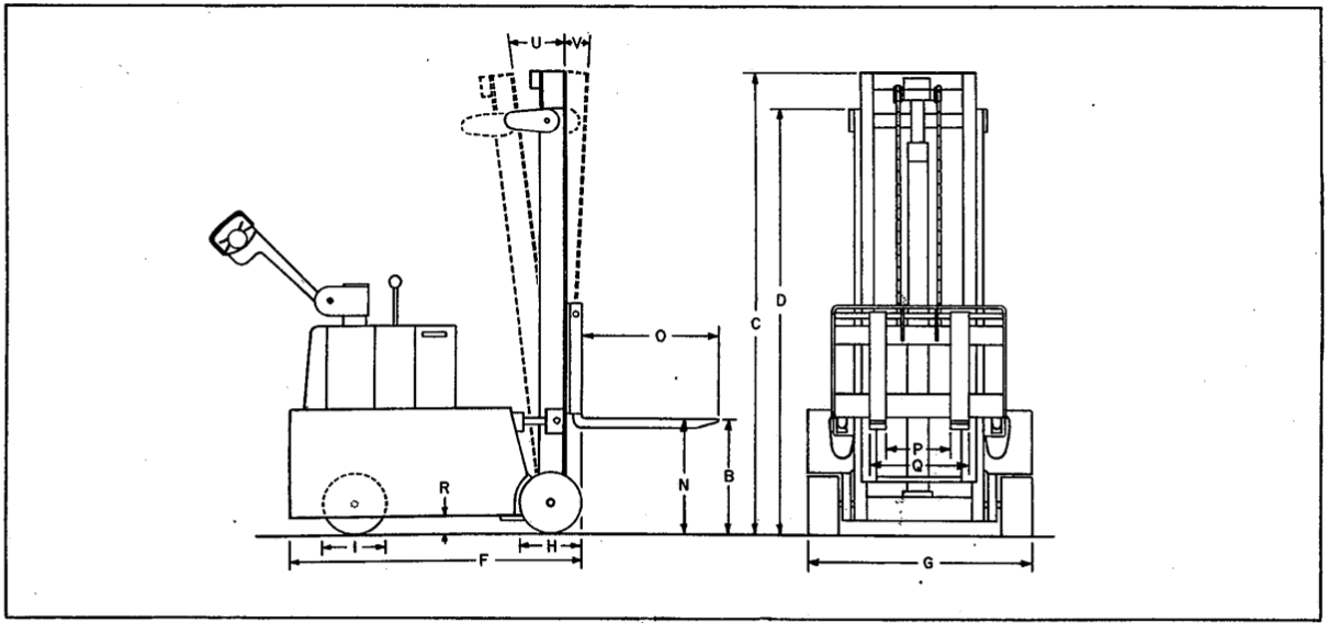
Technical terms or terms not commonly used are defined in Table A. Table B is a table of specifications for the power driven, counterbalanced series. The table contains information on the drive motor, transmission, electrical system, hydraulic system, and wheels as well as overall physical dimensions and mechanical ratings. This data pertains to all counterbalanced units. The characteristics are listed either giving the minimum and maximum measurements or specific dimensions, as applicable. The first column of the table of specifications is keyed to figure A.

Figure A. Power Driven, Counterbalanced, Tilt-mast Lift Truck, Outline
Table A. Glossary of Technical and Special Terms or Terms Not Commonly Used
TERM |
DEFINITION |
Load Center |
Used with a weight specification to establish safe capacities, it is half the length of the load to be lifted. This is based on placing the load against the back rest. |
Free Lift |
Amount of upward movement of forks before mast height increases. |
Front of lift truck |
The fork or platform end. |
Plugging |
Reversal of the drive motor to a low speed in the opposite direction of travel. Permits stopping and changing direction of travel very rapidly. |
Table B. Table of Specifications
|
|
This column provides general data and operating characteristics for PDCPT list trucks. |
This column is for a record of specific data applicable to your equipment. |
FIG. A DESIG. |
SPECIFICATION |
STANDARD |
Model no._______________ Serial No._______________ |
|
1.GENERAL. |
|
|
|
Max capacity at 24 in. load center |
|
|
|
PDCBT20 |
2000 lb |
|
|
PDCBT25 |
2500 lb |
|
|
PDCBT30 |
3000 lb |
|
|
*Gross wt (w/battery and no load) |
3000 to 4500 lb |
|
|
*Travel speed |
2-1/2 to 3-1/2 mph loaded |
|
|
Maximum lifting speed |
20 fpm loaded, 30 fpm empty |
|
|
Lowering speed |
Variable control, 0-40 fpm loaded |
|
|
Grade Ability |
10% test, 5% working |
|
B |
*Lifting height (to top of forks) Overall dimensions |
54 to 142 in. |
|
C |
*Extended height (forks up) |
72 to 159-1/2 in. |
|
D |
*Collapsed height (forks down) |
59-1/2 to 89-1/2 in. |
|
F |
*Length (to face of forks) |
55 to 76 in. |
|
G |
Width……………Wheels |
36 in. |
|
H |
Load wheels |
10-1/2 in. dia rubber (on trucks with Serial No. 50716 and higher) |
|
|
|
10 in. dia rubber (on trucks with Serial No. 50715 and lower) |
|
I |
Drive wheel |
10-1/2 in. dia polyurethane (on trucks with Serial No. 50716 and higher) |
|
|
|
10 in. dia polyurethane (on trucks with Serial No. 50715 and lower) |
|
N |
Lowered height of forks |
2 in. |
|
O |
Length of forks |
26 in. |
|
P |
Distance between forks (min) |
6 in. |
|
Q |
Outside width of forks (max) |
24 in. |
|
R |
Underclearance |
2-1/2 in. |
|
U |
Rear tilt |
9 degrees |
|
V |
Forward tilt |
3 degrees |
|
*Variable with lift truck capacity and lifting height. | |||
|
2. DRIVE MOTOR |
|
|
|
Type |
Series wound, high torque, reversible |
|
|
Voltage rating |
12 vdc |
|
|
Current rating |
90 to 280 amp (dependent upon load) |
|
|
Horsepower rating |
3 hp |
|
|
3. TRANSMISSION |
|
|
|
Type |
Single speed, double gear reduction |
|
|
Gear ratio |
18.4/1 |
|
|
4. ELECTRICAL SYSTEM |
|
|
|
Battery: |
|
|
|
Voltage rating |
12 volts |
|
|
Ampere-hour capacity |
360 amp at 6 hr rate (PDCBT20) |
|
|
|
432 amp at 6 hr rate (PDCBT25) |
|
|
|
510 amp at 6 hr rate (PDCBT30) |
|
|
5. HYDRAULIC SYSTEM |
|
|
|
Motor: |
|
|
|
Type |
2000 capacity – ML, 2500, 3000 cpacity – MDR |
|
|
Rating |
12 vdc |
|
|
Pump: |
|
|
|
Type |
Gear |
|
|
Rating |
2000 psi |
|
|
Hydraulic oil: |
|
|
|
Type |
150 Saybolt Universal seconds viscosity |
|
|
Quantity |
7 quarts |
|
|
6. OPTIONS AND ACCESORIES |
|
|
|
|
|
|
|
|
|
|

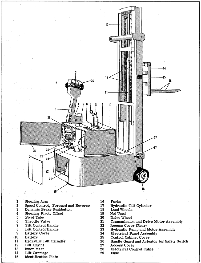
Figure 1-1. Power Driven, Counterbalanced, Tilt-mast Lift Truck
CHAPTER 1
INTRODUCTION AND DETAILED DESCRIPTION
1-1. INTRODUCTION.
This manual contains information necessary to install, operate, and maintain Big Joe Power Driven Counterbalanced Lift Trucks such as models PDCBT20-( ), PDCBT25-( ), and PDCBT30-( ).
The model number is significant in describing the lift truck. The letter and number combination preceding the dash describes the type and capacity (in hundred pounds). The numerals after the dash give the lifting height in inches. For example: PDCBT30-102 is a Power Driven, Counterbalanced lift truck with a Tiltable mast. It has a lifting capacity of 3000 pounds and a lifting height of 102 inches from the floor.
1-2. DESCRIPTION OF MANUAL.
This technical manual has a preface of general data for quick reference, five chapters of descriptive and instructional information, and addenda for special features and modifications. Chapter one gives the detailed description of the major assemblies and accessories. Chapter two provides instructions for checking the equipment when it is received and preparing it for use. Chapter three details the preoperating and operating procedures. The operating procedures are separated into various phases such as pickup, transporting, unloading and parking, including pertinent precautions that extend the life of the lift truck. Chapter four covers preventive maintenance, troubleshooting, corrective maintenance and adjustments. Chapter five contains illustrations and parts lists that aid in locating and identifying replaceable parts. Each addendum should be checked for specific reference to the equipment being serviced.
By following the recommended practices contained in this technical manual, you will derive many years of dependable service from your BIG JOE Lift Trucks.
1-3. DETAILED DESCRIPTION.
1-4. GENERAL.
The power driven, counterbalanced, lift truck efficiently lifts, moves, and stacks heavy objects of various sizes and shapes using simple lever and pushbutton controls. See figure 1-1.
1-5. DRIVE SYSTEM.
A speed control (2) and a dynamic brake pushbutton (3) are located inside the handle guard on the steering arm (1) providing fingertip control for starting and stopping the lift truck. The handle guard activates a safety switch which drives the lift truck forward in low speed, if the reverse drive has caused the handle guard to press against the driver. The speed control provides a choice of any one of three forward speeds and three reverse speeds by operator manipulation.
The lift truck has three wheels: two front wheels, which are load wheels (18), and a steerable drive wheel (20) which propels the lift truck. The speed control and brake pushbutton on the steering arm govern the transmission and drive motor assembly (21) which actuates the drive wheel.
NOTE: The following braking data is applicable to trucks with two-way braking systems (brake actuation with steering arm up or down). Refer to Addendum 1 for trucks with one-way braking systems (brake actuation only when steering arm is up).
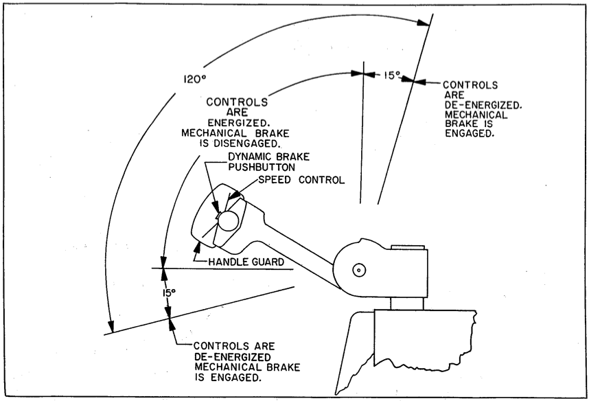
The dynamic brake is the service brake. It is the brake used for stopping the truck during normal operation. The dynamic brake is operable only when the steering arm is lowered from the upright position or raised from a horizontal position. Above or below these points the mechanical brake is actuated. Whenever the mechanical brake is applied all traction power is automatically shut off. When the spring-loaded steering arm is released and returns to the upright position, the mechanical brake is a deadman brake and automatically stops the truck. In this position the mechanical brake is also a parking brake. Pushing the steering arm down below the horizontal position also applies the mechanical brake which in this case is a secondary service brake particularly useful on ramps and tight quarters, See figure 1-2.
1-6. STEERING SYSTEM.
The steering assembly consists of steering arm (1), steering pivot offset (4), pivot tube (5), transmission and drive motor assembly (21), and drive wheel (20). Moving the steering arm to the right or left turns the entire steering assembly. It has a maximum steering arc of 200 degrees. To provide optimum steering lever action when turning the lift truck, position the steering arm at a comfortable operating angle a few degrees above the horizontal plane (see figure 1-2).
NOTE: The following data is applicable to a lift truck with tilt system. Check addendum 2 if your truck does not have a tilt system.
1-7. LIFT AND TILT SYSTEM.
The hydraulic system provides the lifting and tilting power. A large, heavy-duty hydraulic pump and

Figure 1-2. Steering Arm Operation
motor assembly (23) supplies the hydraulic pressure for operation of the lift and tilt mechanisms. The hydraulic pump provides excellent volumetric efficiency over a wide pressure range.
The lift control handle (8) controls up-and-down movement of the forks smoothly and accurately for “inching” and “spotting” of loads. The hydraulic lift cylinder (11) uses two heavy-duty lift chains (12) to raise the lift carriage (14) and forks (16).
The tilt control handle (7) regulates the tilt of the mast and the resulting tilt of the forks. The ability to tilt the mast aids the operator in load placement and load stability. The hydraulic tilt system uses two cylinders (17), one on each side of the mast, to tilt the mast backward or forward.
1-8. ELECTRICAL SYSTEM.
A heavy-duty, industrial battery supplies power to motors for the hydraulic pump, the drive unit, and to all other electrical circuitry. A battery charger is supplied with the lift truck, for recharging the battery. The battery charger automatically decreases the charging rate as the battery approaches full charge.
1-9. OPTIONAL FEATURES.
Remote lift-lower control, horn, and various load attachments are normally available as factory-installed options.
CHAPTER II
INSTALLATION AND TESTS
2-1. GENERAL.
This chapter contains information on receiving, assembling, and testing the lift trucks. The lift truck is usually supplied ready to run with the battery installed and is shipped in one of the following three ways:
1. Driven onto the carrier and the wheels blocked.
2. Skid mounted.
3. Crated.
NOTE: Crating is used primarily for overseas shipments.
2-2. RECEIPT OF LIFT TRUCK.
1. Visually inspect skid, packing or crating for damage, and if any is found, report it to the carrier and to your Big Joe dealer immediately.
CAUTION: TO avoid damaging finished surfaces, do not force pry bar into crate.
2. To uncrate the lift truck, carefully pry open the wooden crate with a pry bar.
3. If lift truck is shipped with a cardboard carton over the mast, remove the carton by lifting it straight up.
4. Cut bands that secure lift truck to skid.
5. Remove and unpack battery charger.
6. Visually inspect truck for physical damage, dents and scratches, which may have occured in shipping.
CAUTION: The hydraulic hoses at the bottom of the truck may be damaged if the truck is removed from the skid by another lift truck. Extreme care must be taken in positioning the lifting forks directly under the solid structural parts of the lift truck being moved.
7. Check to make sure that the lift chains (12, figure 1-1) are secure.
8. Check for oil leaks and loose wiring connections.
NOTE: If any damage is found, report it to the carrier and to your Big Joe dealer immediately.
9. Check battery. Refer to paragraph 2-3 to check battery and connections.
10. Remove blocks from wheels on lift truck.
11. Refer to “Operating Instructions” in Chapter III for driving procedures. Drive lift truck off skid or carrier.
2-3. CHECKING BATTERY AND CONNECTIONS.
Before the truck is moved, the battery must be checked, recharged if necessary, and connected. If the truck was ordered without the battery, a freshly charged 12 v battery must be installed. Proceed as follows to check and connect the lead-acid battery.
1. Open battery cover (9, figure 1-1) and remove loose end battery cable.
2. Remove cap from each cell of battery and make a specific gravity check of electrolyte with a hydrometer.
NOTE: The specific gravity reeading should be above 1250.
3. If the specific gravity reading is less than 1250, recharge battery according to the instructions given in the “Battery Care” section of Chapter IV.
4. When battery is properly charged, plug battery cable quick-disconnect plug into receptacle located near the battery on the base of the lift truck.
2-4. INSTALLATION TETS.
Before using the lift truck for lifting, moving, and stacking of heavy materials, perform the following tests. If you do not obtain the proper results in the following tests, or if improper operation occurs, refer to the “Corrective Maintenanace” section in Chapter IV.
2-5. STEERING ARM SPRING TENSION TEST.
1. Lower steering arm to a horizontal position.
2. Release steering arm.
CAUTION: Do not continuously let the steering arm snap up because damage to the return spring may result.
3. Steering arm must return to its upright position, but if it snaps up abruptly, adjust spring tension in accordance with paragraph 4-9g.
2-6. DRIVING CONTROLS TEST. (Figure 2-1.)
Be sure there is ample floor space for driving the lift truck forward and in reverse while testing the electrical controls. To activate the electrical controls, the steering arm must be lowered at least 15 degrees from its upright position. Refer to figure 1-2.
1. Grasp handle of steering arm so that you can operate the speed control and dynamic brake pushbutton with your thumb.
2. Lower steering arm to a comfortable position above its horizontal plane.
NOTE: According to commercial standards, the front of the lift truck is that part which holds the load.
3. To travel forward, slowly press the top of the speed control.
4. As truck moves forward, release the speed control and depress the dynamic brake pushbutton.
NOTE: The lift truck slows coming to a gradual stop.
5. To travel backward, slowly press bottom of the speed control and lead the lift truck.
6. As the truck moves in reverse, depress the dynamic brake pushbutton to stop the lift truck.